
Page 166 - Engineered Interfaces in Fiber Reinforced Composites
P. 166
148 Engineered interfaces in fiber reinforced composites
J
0.2 0.4 C
Fiber volume fraction, Vf
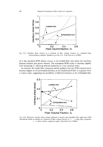
Fig. 4.33. Interface shear stresses as a function of fiber volume fraction, 5, obtained from
micromechanics analysis. Symbols as in Fig. 4.31. After Kim et al. (1994b).
of V, the maximal IFSS always occurs at the loaded fiber end where the interface
debond initiates and grows inward. The maximum IFSS tends to increase slightly
with increasing 6, allowing debond initiation at a low external stress.
In contrast, the single fiber composite model predicts that the IFSS concentration
becomes higher at the embedded end than at the loaded end if fiber vf is greater than
a critical value, suggesting the possibility of debond initiation at the embedded fiber
0,3
-
/"
v) /
cn Loaded end /
.c, E) -&-A P A 4
2 a 0.2- *A
a, -. /
c -\ /
\
v) /
0
Q, - ,A a
8 0.1 - ~ --
't --2 -a
- 0 ,O's Embedded end
a,
C
c,
3g-A-
A-Ap