
Page 169 - Engineered Interfaces in Fiber Reinforced Composites
P. 169
Chapter 4. Micrumechanic.s of stress transjer 151
(4.126)
where k5 = cqvf/( 1 + vm), which is an approximate form of t.-: coefficient k given in
Section 4.2.3.
There are many features in the analysis of the fiber push-out test which are similar
to fiber pull-out. Typically, the conditions for interfacial debonding are formulated
based on the two distinct approaches, i.e., the shear strength criterion and the
fracture mechanics approach. The fiber push-out test can be analyzed in exactly the
same way as the fiber pull-out test using the shear lag model with some
modifications. These include the change in the sign of the IFSS and the increase
in the interfacial radial stress, ql(a,z), which is positive in fiber push-out due to
expansion of the fiber. These modifications are required as a result of the change in
the dircction of the external stress from tension in fiber pull-out to compression in
fiber push-out.
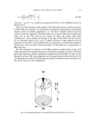
For the cylindrical coordinates of the fiber push-out model shown in Fig. 4.36
where the external (compressive) stress is conveniently regarded as positive, the basic
governing equations and the equilibrium equations are essentially the same as the
fiber pull-out test. The only exceptions are the equilibrium condition of Eq. (4.15)
and the relation between the IFSS and the resultant interfacial radial stress given by
Eq. (4.29), which are now replaced by:
2b
Fig. 4.36. Schematic drawing of the partially debonded fiber in fiber push-out test.