
Page 170 - Engineered Interfaces in Fiber Reinforced Composites
P. 170
152 Engineered interfaces in jiber reinforced composites
(4.127)
In the same procedure as that employed for the fiber pull-out test, the solutions for
stress distributions are obtained in the bonded region, which are exactly the same as
those given in Eqs. (4.90k(4.92). The solutions for the stress distributions in the
debonded regions are:
af(z) = a - ~(8 + a)[l - exp(-h)] , (4.129)
of.,(.) = yo(^+ a)[l - exp(-h)] , (4.130)
(4.13 1)
(4.132)
In these equations, the crack tip debond stress, ce, at the boundary between the
bonded and debonded regions is given by
ae=o-o(a+a)[l -exp(-H)] . (4.133)
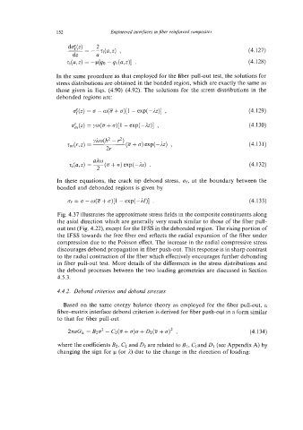
Fig. 4.37 illustrates the approximate stress fields in the composite constituents along
the axial direction which are generally very much similar to those of the fiber pull-
out test (Fig. 4.22), except for the IFSS in the debonded region. The rising portion of
the IFSS towards the free fiber end reflects the radial expansion of the fiber undcr
compression due to the Poisson effect. The increase in the radial compressive stress
discourages debond propagation in fiber push-out. This response is in sharp contrast
to the radial contraction of the fiber which effectively encourages further debonding
in fiber pull-out test. More details of the differences in the stress distributions and
the debond processes between the two loading geometries are discussed in Section
4.5.3.
4.4.2. Debond criterion and dehond stresses
Based on the same energy balance theory as employed for the fiber pull-out, a
fiber-matrix interface debond criterion is derived for fiber push-out in a form similar
to that for fiber pull-out
2naGi, = B202 - Cz(5 + a)a + D2(8 + a)2 , (4.134)
where the coefficients B2, C2 and 02 are related to BI, Cland D1 (see Appendix A) by
changing the sign for p (or 2) due to the change in the direction of loading: