
Page 165 - Engineered Interfaces in Fiber Reinforced Composites
P. 165
Chapter 4. Micromechanics of stress transfer 147
lm2 I
1
tn
tn
0.8
-
tn
-# 0.6
5 0.4
n
LL
0.2
0
0 0.2 0.4 0.6 0.8 1.0
" 0 0.2 0.4 0.6 0.8 1.0
(b) Axial distance, z/L
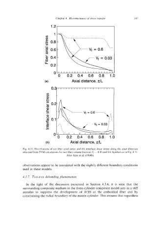
Fig. 4.32. Distributions of (a) fiber axial stress and (b) interface shear stress along the axial direction
obtained from FEM calculations for two fiber volume fraction, V, = 0.03 and 0.6. Symbols as in Fig. 4.3 1.
After Kim et al. (1994b).
observations appear to be associated with the slightly different boundary conditions
used in these models.
4.3.7. Two-M1ay debonding phenomenon
In the light of the discussion presented in Section 4.3.6, it is seen that the
surrounding composite medium in the three-cylinder composite model acts as a stiff
annulus to suppress the development of IFSS at the embedded fiber end by
constraining the radial boundary of the matrix cylinder. This ensures that regardless