
Page 163 - Engineered Interfaces in Fiber Reinforced Composites
P. 163
Chapter 4. Micromechanics of stress transfer 145
- Fiber
Fiber
Matrix
Composite
medium
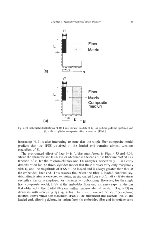
Fig. 4.30. Schematic illustrations of the finite element models of (a) single fiber pull-out specimen and
(b) a three cylinder composite. After Kim et al. (1994b).
increasing 6. It is also interesting to note that the single fiber composite model
predicts that the IFSS obtained at the loaded end remains almost constant
regardless of 6.
The pronounced effect of fiber 6 is further manifested in Figs. 4.33 and 4.34,
where the characteristic IFSS values obtained at the ends of the fiber are plotted as a
function of 6 for the micromechanics and FE analyses, respectively. It is clearly
demonstrated for the three- cylinder model that these stresses vary only marginally
with 6, and the magnitude of IFSS at the loaded end is always greater than that at
the embedded fiber end. This ensures that when the fiber is loaded continuously,
debonding is always expected to initiate at the loaded fiber end for all 6, if the shear
strength criterion is employed for the interface debonding. However, for the single
fiber composite model, IFSS at the embedded fiber end increases rapidly whereas
that obtained at the loaded fiber end either remains almost constant (Fig. 4.33) or
decreases with increasing 6 (Fig. 4.34). Therefore, there is a critical fiber volume
fraction above which the maximum IFSS at the embedded end exceeds that of the
loaded end, allowing debond initiation from the embedded fiber end in preference to