
Page 361 - Engineered Interfaces in Fiber Reinforced Composites
P. 361
342 Engineered interfaces in jber reinforced composites
tn
a
Q)
c
E
3i ,,
I
!j 0.6
U i
-5 0.4
Q,
0.2
nl I I I
"40 50 60 70 80
Crack length, a (mm)
Fig. 8.1 I. Residual stiffness as a function crack length as measured from double cantilever beam
specimens after impact damage: Carbon fiber composites containing (0) unmodified epoxy; (0) rubber-
modified epoxy. After Kim et al. (1993).
8.3. Delamination resisters
8.3.1. Mechanics of.free edge delamination
Delamination along the free edge of composite laminates under in-plane axial
loading has been a subject of great importance, and much work has been reported in
the literature (Pipes and Pagano, 1970; Pagano and Pipes, 1973; Whitney and
Browning, 1973; Hsu and Herakovich, 1977; Pagano and Soni, 1983; Kim, 1989).
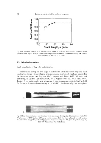
Typical X-ray radiography and ultrasonic C-scan images are presented in Fig. 8.12
for free-edge delamination occurring in ( f 30°/900),s laminates subjected to in-plane
Delamination
- -.
a
Fig. 8.12. (a) X-ray radiograph and (b) ultrasonic C-scan image, showing edge delamination in the [ f 30°/
90"], laminate of T300 carbon-5208 epoxy matrix system which has been subjected to axial tension.
Reprinted from Kim (1989), with kind permission from Elsevier Science-NL, Sara Burgerhart straat 25,
1055 KV Amsterdam, The Netherlands.