
Page 69 - Engineered Interfaces in Fiber Reinforced Composites
P. 69
52 Engineered interfaces in jber reinforced composites
(b)
f
Restrained
, bottom
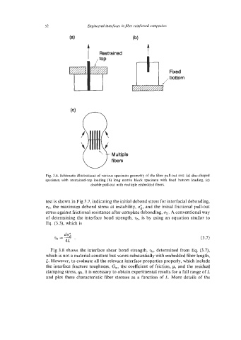
Fig. 3.6. Schematic illustrations of various specimen geometry of the fiber pull-out test: (a) disc-shaped
specimen with restrained-top loading (b) long matrix block specimen with fixed bottom loading, (c)
double pull-out with multiple embedded fibers.
test is shown in Fig 3.7, indicating the initial debond stress for interfacial debonding,
00, the maximum debond stress at instability, cri, and the initial frictional pull-out
stress against frictional resistance after complete debonding, ofr. A conventional way
of determining the interface bond strength, tb, is by using an equation similar to
Eq. (3.3), which is
Fig 3.8 shows the interface shear bond strength, Tb, determined from Eq. (3.7),
which is not a material constant but varies substantially with embedded fiber length,
L. However, to evaluate all the relevant interface properties properly, which include
the interface fracture toughness, Gic, the coefficient of friction, p, and the residual
clamping stress, 40, it is necessary to obtain experimental results for a full range of L
and plot these characteristic fiber stresses as a function of L. More details of the