
Page 71 - Engineered Interfaces in Fiber Reinforced Composites
P. 71
54 Engineered interfaces in jiber reinforced composites
I I I 1 1
0 100 200 300 400 I 10
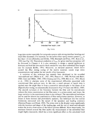
(b) Embedded fiber length, Lbm)
Fig. 3.8.(b).
large data scatter especially for composite systems with strong interface bonding and
small fiber diameters. For example, for the carbon fiber-epoxy matrix system L,,, is
less than 1.0 mm (Pitkethly and Doble, 1990; Marshall and Price, 1991; Kim et al.,
1992) (see Fig 3.8). Theoretical prediction of L,,, for given interface properties will
be discussed in Chapter 4. It is also necessary to design a special jig/fixture to
fabricate and hold the thin matrix block needed for very short embedded fiber length
(see for example Baillie, 1991). Moreover, an elevated meniscus, which forms
around the fiber during curing of the matrix material, causes large stress
concentrations and makes the test results often inaccurate.
A variation of this technique has recently been developed in the so-called
'microdebond test' (Miller et al., 1987, 1991; Penn et al., 1988; McAlea and Besio,
1988; Gaur and Miller, 1989, 1990; Chuang and Chu, 1990; Biro et al., 1991; Moon
et al., 1992) to alleviate some of the experimental difficulties associated with
conventional fiber pull-out tests. In this test, a small amount of liquid resin is
applied onto the single fiber to form a concentric microdroplet in the shape of an
ellipsoid after curing, as schematically illustrated in Fig 3.9 (Gaur and Miller, 1989).
The smooth curvature at the boundary between the fiber and the microdroplet
reduces the stress concentration at the fiber entry to a certain extent and, hence, the
large variation in the experimental data is also reduced. The microdebond technique
can be used for almost any combination of fiber and polymer matrices. However, as
found in finite element and photoelastic analyses, this technique also has serious
limitations associated with the nature of the specimen and loading condition
(Herrera-Franco and Drzal, 1992). The stress state in the droplet varies significantly
with the location and shape of the loading jigs, and the size of small microdroplet
makes the in-situ observation of the failure process difficult. More importantly, the
meniscus formed around the fiber makes the measurement of the embedded fiber
length highly inaccurate, which has a more significant effect on the calculated bond