
Page 109 - Engineering Digital Design
P. 109
80 CHAPTER 3 / BACKGROUND FOR DIGITAL DESIGN
and O's, these descriptors take the following meaning:
Logic 1 is the ACTIVE state
Logic 0 is the INACTIVE state
Thus, in the logic domain, logic 1 is assigned to the active condition while logic 0 is assigned
to the inactive condition. This will always be so.
A symbol that is attached to the name of a signal and that establishes which physical
state, HV or LV, is to be the active state for that signal, is called the activation level indicator.
The activation level indicators used in this text are
(/O meaning ACTIVE HIGH
(L) meaning ACTIVE LOW
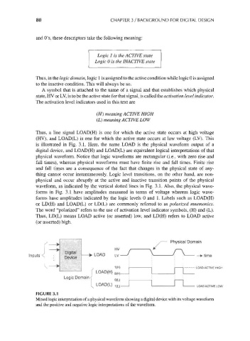
Thus, a line signal LOAD(H) is one for which the active state occurs at high voltage
(HV), and LOAD(L) is one for which the active state occurs at low voltage (LV). This
is illustrated in Fig. 3.1. Here, the name LOAD is the physical waveform output of a
digital device, and LOAD(H) and LOAD(L) are equivalent logical interpretations of that
physical waveform. Notice that logic waveforms are rectangular (i.e., with zero rise and
fall times), whereas physical waveforms must have finite rise and fall times. Finite rise
and fall times are a consequence of the fact that changes in the physical state of any-
thing cannot occur instantaneously. Logic level transitions, on the other hand, are non-
physical and occur abruptly at the active and inactive transition points of the physical
waveform, as indicated by the vertical dotted lines in Fig. 3.1. Also, the physical wave-
forms in Fig. 3.1 have amplitudes measured in terms of voltage whereas logic wave-
forms have amplitudes indicated by the logic levels 0 and 1. Labels such as LOAD(H)
or LD(H) and LOAD(L) or LD(L) are commonly referred to as polarized mnemonics.
The word "polarized" refers to the use of activation level indicator symbols, (H) and (L).
Thus, LD(L) means LOAD active (or asserted) low, and LD(H) refers to LOAD active
(or asserted) high.
/— Physical Domain
HV / \ r\
Inputs < - ^™' h-* LOAD LV-^ > 1 > ->time
1(H) i 1 | 1 LOAD ACTIVE HIGH
|
LOAD(H) 0(H)
Logic Domain ^
LOAD(L) 1(L)
LOAD ACTIVE LOW
FIGURE 3.1
Mixed logic interpretation of a physical waveform showing a digital device with its voltage waveform
and the positive and negative logic interpretations of the waveform.