
Page 110 - Engineering Digital Design
P. 110
3.2 BINARY STATE TERMINOLOGY AND MIXED LOGIC NOTATION 81
Voltage noise margins
NMH
Region of Uncertainty
NML H
Positive Logic Negative Logic
(a) (b)
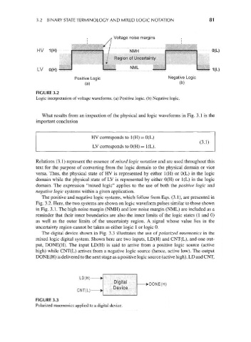
FIGURE 3.2
Logic interpretation of voltage waveforms, (a) Positive logic, (b) Negative logic.
What results from an inspection of the physical and logic waveforms in Fig. 3.1 is the
important conclusion
HV corresponds to 1(H) = 0(L)
(3.1)
LV corresponds to 0(H) = 1(L).
Relations (3.1) represent the essence of mixed logic notation and are used throughout this
text for the purpose of converting from the logic domain to the physical domain or vice
versa. Thus, the physical state of HV is represented by either 1(H) or 0(L) in the logic
domain while the physical state of LV is represented by either 0(H) or 1(L) in the logic
domain. The expression "mixed logic" applies to the use of both the positive logic and
negative logic systems within a given application.
The positive and negative logic systems, which follow from Eqs. (3.1), are presented in
Fig. 3.2. Here, the two systems are shown on logic waveform pulses similar to those shown
in Fig. 3.1. The high noise margin (NMH) and low noise margin (NML) are included as a
reminder that their inner boundaries are also the inner limits of the logic states (1 and 0)
as well as the outer limits of the uncertainty region. A signal whose value lies in the
uncertainty region cannot be taken as either logic 1 or logic 0.
The digital device shown in Fig. 3.3 illustrates the use of polarized mnemonics in the
mixed logic digital system. Shown here are two inputs, LD(H) and CNT(L), and one out-
put, DONE(H). The input LD(H) is said to arrive from a positive logic source (active
high) while CNT(L) arrives from a negative logic source (hence, active low). The output
DONE(H) is delivered to the next stage as a positive logic source (active high). LD and CNT,
DONE(H)
FIGURE 3.3
Polarized mnemonics applied to a digital device.