
Page 157 - Engineering Digital Design
P. 157
128 CHAPTER 3 / BACKGROUND FOR DIGITAL DESIGN
0(L)
B(H)
2
Y X(L) «J S
(a) (b)
M
C(L)
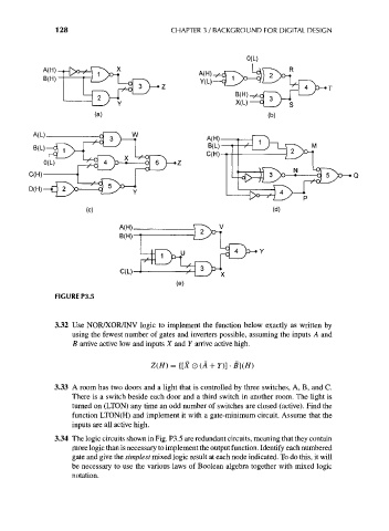
FIGURE P3.5
3.32 Use NOR/XOR/INV logic to implement the function below exactly as written by
using the fewest number of gates and inverters possible, assuming the inputs A and
B arrive active low and inputs X and Y arrive active high.
Z(H) = {[X O (A + Y)] • B}(H)
3.33 A room has two doors and a light that is controlled by three switches, A, B, and C.
There is a switch beside each door and a third switch in another room. The light is
turned on (LTON) any time an odd number of switches are closed (active). Find the
function LTON(H) and implement it with a gate-minimum circuit. Assume that the
inputs are all active high.
3.34 The logic circuits shown in Fig. P3.5 are redundant circuits, meaning that they contain
more logic than is necessary to implement the output function. Identify each numbered
gate and give the simplest mixed logic result at each node indicated. To do this, it will
be necessary to use the various laws of Boolean algebra together with mixed logic
notation.