
Page 424 - Engineering Digital Design
P. 424
394 CHAPTER 9 / PROPAGATION DELAY AND TIMING DEFECTS
Hazard Cover
BC
10
A(H)
AB(L) I
AC(L) J
BC(L)
(b) (c)
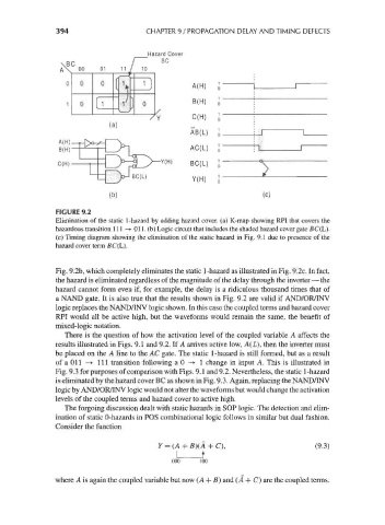
FIGURE 9.2
Elimination of the static 1-hazard by adding hazard cover, (a) K-map showing RPI that covers the
hazardous transition 111 —*• 011. (b) Logic circuit that includes the shaded hazard cover gate BC(L).
(c) Timing diagram showing the elimination of the static hazard in Fig. 9.1 due to presence of the
hazard cover term BC(L).
Fig. 9.2b, which completely eliminates the static 1-hazard as illustrated in Fig. 9.2c. In fact,
the hazard is eliminated regardless of the magnitude of the delay through the inverter — the
hazard cannot form even if, for example, the delay is a ridiculous thousand times that of
a NAND gate. It is also true that the results shown in Fig. 9.2 are valid if AND/OR/INV
logic replaces the NAND/INV logic shown. In this case the coupled terms and hazard cover
RPI would all be active high, but the waveforms would remain the same, the benefit of
mixed-logic notation.
There is the question of how the activation level of the coupled variable A affects the
results illustrated in Figs. 9.1 and 9.2. If A arrives active low, A(L), then the inverter must
be placed on the A line to the AC gate. The static 1-hazard is still formed, but as a result
ofaOll —> 111 transition following a 0 -> 1 change in input A. This is illustrated in
Fig. 9.3 for purposes of comparison with Figs. 9.1 and 9.2. Nevertheless, the static 1-hazard
is eliminated by the hazard cover BC as shown in Fig. 9.3. Again, replacing the NAND/INV
logic by AND/OR/INV logic would not alter the waveforms but would change the activation
levels of the coupled terms and hazard cover to active high.
The forgoing discussion dealt with static hazards in SOP logic. The detection and elim-
ination of static 0-hazards in POS combinational logic follows in similar but dual fashion.
Consider the function
Y = (A + B)(A + C), (9.3)
000 100
where A is again the coupled variable but now (A + B) and (A + (7) are the coupled terms.