
Page 425 - Engineering Digital Design
P. 425
9.2 STATIC HAZARDS IN TWO-LEVEL COMBINATIONAL LOGIC CIRCUITS 395
Hazard Cover
BC
10
C(H)
F^ I
BC(L)
Small region of logic 0
(b) (c)
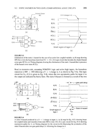
FIGURE 9.3
Elimination of the static 1-hazard for the case of an active low coupled variable, (a) K-map showing
RPI that covers the hazardous transition Oil —>• 111. (b) Logic circuit that includes the shaded hazard
cover gate BC(L). (c) Timing diagram showing the elimination of the static 1-hazard due to presence
of the hazard cover term fiC(L).
Read in maxterm code, assuming NOR/INV logic and active high inputs, the hazardous
transition is 000 —»• 100 following a 0 -> 1 change in A as shown in Fig. 9.4a. The logic
circuit for Eq. (9.3) is given in Fig. 9.4b, where the two asymmetric paths for input A to
the output are indicated by heavy lines. The static 0-hazard is formed as a result of the two
«— r = gate path delay
A(H) 1 o
o ) 1 1
I \
0 1 3 2 B(H)
— » fT~
0 1 1
C(H)
4 5 7 6
L
(a) Y ( A+B X > i
(A+C)(L) i
A
Y(H)
Y(H)
Static 0-hazard
Small region of
Iog|c1 —, N V
(b) (c)
FIGURE 9.4
A static 0-hazard produced by a 0 —>• 1 change in input A. (a) K-map for Eq. (9.3) showing loops
for coupled terms and transition from state 000 to state 100. (b) Logic circuit for Eq. (9.3) showing
asymmetric paths for A. (c) Timing diagram for the circuit in (b) illustrating the production of the
static 0-hazard after two gate path delays 2r following the change in A.