
Page 520 - Engineering Digital Design
P. 520
490 CHAPTER 10 / INTRODUCTION TO SYNCHRONOUS STATE MACHINE DESIGN
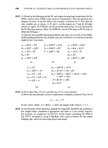
10.23 (1) Shown in the following are the NS- and output-forming logic expressions for five
FSMs. Analyze these FSMs to the extent of constructing a fully documented state
diagram for each. To do this follow the examples in Section 10.13. Note that the
state variables are, as always, A, B, and C, and the outputs are P and Q. All other
literals are inputs. For FSM (d), use the excitation table in Fig. 10.5a to characterize
the FG flip-flop memory. (Hint: For FSM (d), convert D K-maps to FG K-maps to
obtain the NS logic.)
(2) Indicate any possible branching problems that may exist in each of the FSMs.
Such branching problems may include states for which there is no entrance and that
might be don't care states.
J A = BXY + XY TA = ABXY + AXY J A = BXY + BXY
KA = BXY + BXY T B = ABXY + BY K A = BX + XYZ
J =AX + XY P =ABX + AB J =A(X + Z)
B
B
K = XY K = AY
B
B
Q = ABX + BX Q = BXY + ABY
(a) (b) (c)
ABC
P=BX+A P = BCSY + ABC
Q = ACN
(d) (e)
10.24 (a) Prove that if Eq. (10.4) is satisfied, Eq. (10.3) is also satisfied.
(b) Prove that the mutually exclusive requirement is uniquely satisfied in Fig. 10.8 if
fi^j • /*<-; = °
for all / and k, where i ^ k. Here i, j, and k are integers with values 0, 1, 2, 3, —
10.25 At the discretion of the instructor, simulate by using EXL-Sim2002 any problem in
this chapter where simulation is appropriate and where it is not already required.
For example, an assignment 10.25/10.13c would require simulating the FSM in
Fig. P10.7c designed by using D flip-flops with a gate-minimum NS and output
forming logic, and with active high inputs and output.