
Page 517 - Engineering Digital Design
P. 517
PROBLEMS 487
Transparent
D Latch
X(H) Q
D Q
CK- > Q
RETD
Flip-flop
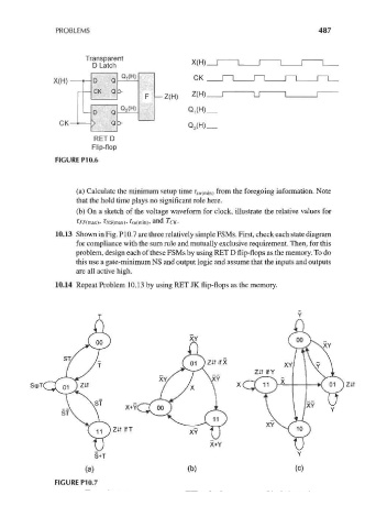
FIGURE P10.6
(a) Calculate the minimum setup time ? SM( min) from the foregoing information. Note
that the hold time plays no significant role here.
(b) On a sketch of the voltage waveform for clock, illustrate the relative values for
), TMS(max), ^w(min), and TCK-
10.13 Shown in Fig. P10.7 are three relatively simple FSMs. First, check each state diagram
for compliance with the sum rule and mutually exclusive requirement. Then, for this
problem, design each of these FSMs by using RET D flip-flops as the memory. To do
this use a gate-minimum NS and output logic and assume that the inputs and outputs
are all active high.
10.14 Repeat Problem 10.13 by using RET JK flip-flops as the memory.
XY
S©T
\ \ QT
X+Yi
ZiT if T