
Page 752 - Engineering Digital Design
P. 752
718 CHAPTER 14 / ASYNCHRONOUS STATE MACHINE DESIGN AND ANALYSIS
At D = 5r p
At F = 5r n
E P
A(H) A(H)
Effect of
B(H) B(H) f d-trio
Effect of
^ E-hazard
y^H) 1 Vl(H) I
— *i r«— (2r n) 3T r
~~^ |*~ ( p ~ !Nv)
y 0(H) 1 V 0(H)
( V 0B(L) ^J LJ
y,A(L) 1 Y 1 < VlA(L) I
r-i
Z(H) | 1
_ Error
V^CL) output
I
(a) (b)
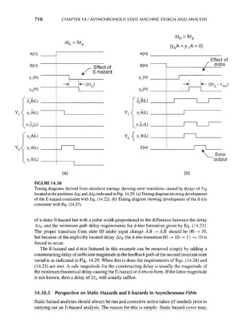
FIGURE 14.30
Timing diagrams derived from simulator tracings showing error transitions caused by delays of 5r p
located at the positions Afe and A?D indicated in Fig. 14.29. (a) Timing diagram showing development
of the E-hazard consistent with Eq. (14.22). (b) Timing diagram showing development of the d-trio
consistent with Eq. (14.23).
of a static 0-hazard but with a pulse width proportional to the difference between the delay
Af/) and the minimum path delay requirements for d-trio formation given by Eq. (14.23).
The proper transition from state 00 under input change AB -> AB should be 00-> 10,
but because of the explicitly located delay At D the d-trio transition 00 -> 10 —> 11-* 10 is
forced to occur.
The E-hazard and d-trio featured in this example can be removed simply by adding a
counteracting delay of sufficient magnitude in the feedback path of the second invariant state
variable as indicated in Fig. 14.29. When this is done the requirements of Eqs. (14.24) and
(14.25) are met. A safe magnitude for the counteracting delay is usually the magnitude of
the minimum theoretical delay causing the E-hazard or d-trio to form. If the latter magnitude
is not known, then a delay of 2r p will usually suffice.
14.10.5 Perspective on Static Hazards and E-hazards in Asynchronous FSMs
Static hazard analyses should always be run and corrective active taken (if needed) prior to
carrying out an E-hazard analysis. The reason for this is simple: Static hazard cover may,