
Page 756 - Engineering Digital Design
P. 756
722 CHAPTER 14 / ASYNCHRONOUS STATE MACHINE DESIGN AND ANALYSIS
4. Collect the TT-partitions into partitions that include all states identifiers. These parti-
tions are called r (total) partitions. If this is properly done, all T-partitions will begin
with the state identifier for the initialization state on the left side of the partition.
5. Find a minimum set of T-partitions that "cover" all n -partitions. The number of T-
partitions is equal to the number of state variables for the FSM. There may be more
than one minimum set of T-partitions. If more than one minimum set of T-partitions
exist, the choice of any one of the minimum sets will lead to an optimum or near
optimum STT design — there is usually little difference in their use. A nonminimum
set of T-partitions will usually not yield an optimum STT design, but it can happen.
6. Select a valid state code assignment from a minimum set of T-partitions. Choose the
initialization state to be either a • • • 000 state or a • • • 111 state, not a mixture. See
Section 14.11 for rules governing the initialization of asynchronous FSMs. Note that
for FSMs lacking cross branching the partitioning method defaults to unit distance
coding of states as in Fig. 14.22.
At this point the array algebraic approach, discussed in Section 11.11, can be used to
obtain the NS and output functions for the STT state machine. The array algebraic approach
discussed here is actually an extension of the LPD model, since the lumped path delays in
the NS functions are implied.
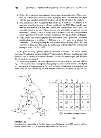
As an example, consider the FSM represented by the state diagram and state table in
Fig. 14.33, presented here for purposes of designing it as an STT state machine. This figure
is a reproduction of that presented in Fig. 14.6, exclusive of state code assignments at this
point. From the state table in Fig. 14.33b, there result the seed sets given by Eqs. (14.26).
S+T
Sanity
ST I 0 IT I 3 I 2
oo 01 11 10 P Q
0 0
ST
ST
ST
V_/ X ' ^_S
S+T
PATifSf (^) indicates a holding condition
Q1T if S ^-^
(a) (b)
FIGURE 14.33
Reproduction of state machine in Fig. 14.6 for purposes of designing it as an STT machine, (a) State
diagram representation, (b) The equivalent state table for the FSM in (a).