
Page 760 - Engineering Digital Design
P. 760
726 CHAPTER 14/ASYNCHRONOUS STATE MACHINE DESIGN AND ANALYSIS
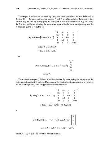
The output functions are obtained by using the same procedure. As was indicated in
Section 11.11, the state matrices for outputs P and Q are obtained directly from the state
table in Fig. 14.33b. By multiplying the transpose of the P state matrix in Fig. 14.33b by
the D matrix and by substituting the appropriate y-variables for the state adjacency sets, the
P function matrix is found to be
0 ae a a
abc 0 0 0
t
F P = P D=[0 0 0 0 Sf] 0 c bed 0
0 bd 0 0
de 0 e bcde
= [de 0 e bcde]ST
or
'/o'
= FpI=[v3>ST 0 y3ji5T yoST]
= y 0ST.
The results for output Q follows in similar fashion. By multiplying the transpose of the
state matrix for output Q with the D matrix and by substituting the appropriate y-variables
for the state adjacency sets, the Q function matrix becomes
0 ae a a
abc 0 0 0
1
= Q D=[0 1 0 ST S] 0 c bed 0
0 bd 0 0
de 0 e bcde
bdST eS bcdeS]
or
~/o'
yoS] f l
A.
+ yoST,
where y^S • /o = yiS • ST — 0 has been eliminated.