
Page 763 - Engineering Digital Design
P. 763
14.12 SINGLE-TRANSITION-TIME MACHINES 729
Hazard
Cover
Hazard
Cover
y 2(H) —
y 0(H) —
T(H) —
A(L)
Hazard f Q(H)
Cover \ E(L)
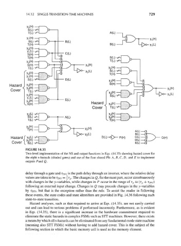
FIGURE 14.35
Two-level implementation of the NS and output functions in Eqs. (14.35) showing hazard cover for
the eight s-hazards (shaded gates) and use of the four shared Pis A, B, C, D, and E to implement
outputs Pand Q.
delay through a gate and T/ NV is the path delay through an inverter, where the relative delay
values are taken to be T//VV = f t p • The changes in Q, for the most part, occur simultaneously
with changes in the y-variables, while changes in P occur in the range of r p to (r p + T//W)
following an external input change. Changes in Q may precede changes in the y-variables
by T/yw, but that is the exception rather than the rule. To assist the reader in following
these events, the state codes and state identifiers are provided in Fig. 14.36 following each
state-to-state transition.
Hazard analyses, such as that required to arrive at Eqs. (14.35), are not easily carried
out and can lead to serious problems if performed incorrectly. Furthermore, as is evident
in Eqs. (14.35), there is a significant increase in the hardware commitment required to
eliminate the static hazards in complex FSMs such as STT machines. However, there exists
a means by which all s-hazards can be eliminated from any fundamental mode state machine
(meaning also STT FSMs) without having to add hazard cover. This is the subject of the
following section in which the basic memory cell is used as the memory element.