
Page 767 - Engineering Digital Design
P. 767
S(H) ^°
T(H) ^O
T(L>—
A(L)-c|>-P(H)
Hazard Cover
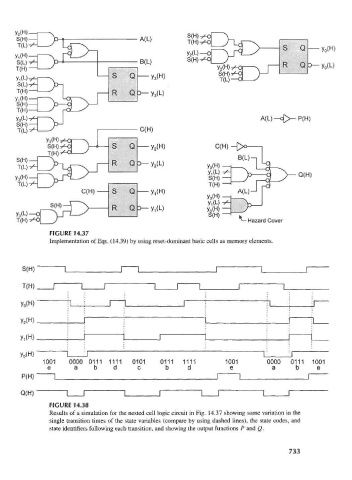
FIGURE 14.37
Implementation of Eqs. (14.39) by using reset-dominant basic cells as memory elements.
S(H)
T(H)
Y 3(H)
y 2(H)
y 0(H) I J L J
1001 0000 0111 1111 0101 0111 1111 1001 0000 0111 1001
e a b d c b d e a b e
P(H) I I I I
Q(H) I I I T
FIGURE 14.38
Results of a simulation for the nested cell logic circuit in Fig. 14.37 showing some variation in the
single transition times of the state variables (compare by using dashed lines), the state codes, and
state identifiers following each transition, and showing the output functions P and Q.
733