
Page 350 - Subyek Computer Aided Design - [David Planchard] Engineering Design with SOLIDWORKS
P. 350
Fundamentals of Drawing Engineering Design with SOLIDWORKS® 2018
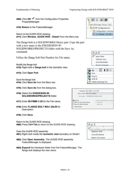
469) Click OK ~ from the Configuration Properties
PropertyManager.
FeatureManager Design Tree
470) Return to the FeatureManager.
• ~ PLATE Configuration(s)
~ ~ Configurat ion Commer
Return to the GU I DE-ROD drawing. I~ ~ Default [ 56-A28 1]
471) Click Window, GUIDE-ROD - Sheet1 from the Menu bar.
The flange bolt is a SOLIDWORKS library part. Copy the part
with a new name to the ENGDESIGN-W-
SOLIDWORKS\PROJECTS folder with the Save As
command.
Select Other
Utilize the flange bolt Part Number for File name.
Selection Tools
Zoom/Pan/Rotate
Modify the flange bolt.
472) Right-click a flange bolt in the Isometric view.
473) Click Open Part.
Save the flange bolt.
474) Click Save As from the Menu bar. (@ Publish eDrawings File
475) Click Save As from the dialog box.
File name: 99- FBMS- 1-25.SLDPRT
476) Select the ENGDESIGN-W- Save as type: Part (*.prt;*.sldprt)
SOLIDWORKS\PROJECTS folder. Description: FLANGE BOLT M8x1 .25x30
@save as Include all referenced compor
477) Enter 99-FBMS-1-25 for the File name.
O Save as copy and continue ~ Add prefix
O Save as copy and open I Add suffix
478) Enter FLANGE BOLT M8x1.25x30 for A Hide Folders
Description.
479) Click Save.
Return to the GUIDE-ROD drawing.
FR
480) Press Ctrl+Tab to return to the GUIDE-ROD drawing. b($ d [j
,
V\}
• .
Open Assembly (guide-rod.sldasr
Open the GUIDE-ROD assembly. Selection Tools '
481) Right-click inside the Isometric view boundary on Sheet1. Zoom/Pan/ Rotate '
Recent Commands '
482) Click Open Assembly. The GUIDE-ROD assembly
FeatureManager is displayed.
483) Expand the Hardware folder from the FeatureManager. The
flange bolt displays the new name.
PAGE4 - 74