Page 352 - Subyek Computer Aided Design - [David Planchard] Engineering Design with SOLIDWORKS
P. 352

Fundamentals of Drawing                                                                                                                                    Engineering Design with SOLIDWORKS® 2018


                                                  )$1'·~  ~


                                                 ~  ~)                                                                                                                                                                                                              tE

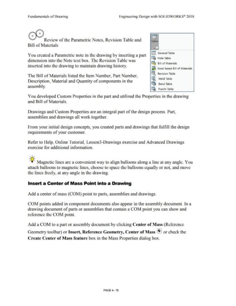
                                                 ~..,,.,                    Review of the Parametric Notes, Revision Table and                                                                                                                                   Tables


                                                Bill of Materials
                                                                                                                                                                                                                                                                          "'

                                                                                                                                                                                                                                                                      ...  I\~


                                                                                                                                                                                                                                                                  IE  General Table
                                                You created a Parametric note in the drawing by inserting a part


                                                                                                                                                                                                                                                                  ~ Hole Table
                                                dimension into the Note text box. The Revision Table was


                                                                                                                                                                                                                                                                  ~ Bill  of Materials
                                                inserted into the drawing to maintain drawing history.

                                                                                                                                                                                                                                                                  fi Excel based  Bill  of Materials


                                                                                                                                                                                                                                                                  ~ Revision Table
                                                The Bill of Materials listed the Item Number, Part Number,


                                                                                                                                                                                                                                                                  II,,  Weld Table
                                                Description, Material and Quantity of components in the


                                                                                                                                                                                                                                                                  ~ Bend Table
                                                assembly.

                                                                                                                                                                                                                                                                  ~ Punch Table


                                                You developed Custom Properties in the part and utilized the Properties in the drawing


                                                and Bill of Materials.


                                                Drawings and Custom Properties are an integral part of the design process. Part,


                                                assemblies and drawings all work together.


                                                From your initial design concepts, you created parts and drawings that fulfill the design


                                                requirements of your customer.


                                                Refer to Help, Online Tutorial, Lesson3-Drawings exercise and Advanced Drawings


                                                exercise for additional information.


                                                   '  I /


                                                  ;Q~ Magnetic lines are a convenient way to align balloons along a line at any angle. You


                                                attach balloons to magnetic lines, choose to space the balloons equally or not, and move


                                                the lines freely, at any angle in the drawing.


                                                Insert a Center of Mass Point into a Drawing


                                                Add a center of mass (COM) point to parts, assemblies and drawings.


                                                COM points added in component documents also appear in the assembly document. In a


                                                drawing document of parts or assemblies that contain a COM point you can show and


                                                reference the COM point.


                                                Add a COM to a part or assembly document by clicking Center of Mass (Reference


                                                Geometry toolbar) or Insert, Reference Geometry, Center of Mass l!.I or check the


                                                Create Center of Mass feature box in the Mass Properties dialog box.


                                                                                                                                                                                PAGE4 - 76
   347   348   349   350   351   352   353   354   355   356   357