
Page 354 - Subyek Computer Aided Design - [David Planchard] Engineering Design with SOLIDWORKS
P. 354
Fundamentals of Drawing Engineering Design with SOLIDWORKS® 2018
Project Summary
In this Project you developed two drawings: GUIDE drawing and the GUIDE-ROD
assembly drawing. The drawings contained three standard views, (principle views) and
an Isometric view. The drawings utilized a custom Sheet Format containing a Company
logo, Title block and Custom Properties. You incorporated the GUIDE part dimensions
into the drawing.
The Drawing toolbar contained the Model View tool and the Projected View tool to
develop standard views. Additional views were required and utilized the Auxiliary, Detail
and Section view tools. Dimensions were inserted from the part and added to the
drawing.
You used two major design modes in the drawings: Edit Sheet Format and Edit Sheet.
The detailed GUIDE drawing included annotations and Custom Properties. The GUIDE-
ROD assembly drawing incorporated a Bill of Materials and additional Custom
Properties.
AnnoLaLIOn Lin"' vanau,es
, ,/ I~ I Decals
ffi Grid
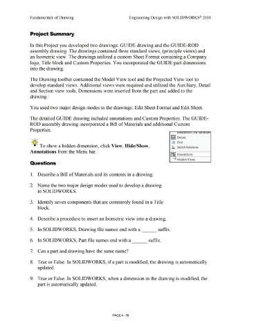
~Q;. To show a hidden dimension, click View, Hide/Show,
.Ii Sketch Relations
Annotations from the Menu bar.
Af~ Annotations
"• Hidden Views
Questions
1. Describe a Bill of Materials and its contents in a drawing.
2. Name the two major design modes used to develop a drawing
in SOLIDWORKS.
3. Identify seven components that are commonly found in a Title
block.
4. Describe a procedure to insert an Isometric view into a drawing.
5. In SOLIDWORKS, Drawing file names end with a ___ suffix.
6. In SOLIDWORKS, Part file names end with a suffix.
---
7. Can a part and drawing have the same name?
8. True or False. In SOLIDWORKS, if a part is modified, the drawing is automatically
updated.
9. True or False. In SOLIDWORKS, when a dimension in the drawing is modified, the
part is automatically updated.
PAGE4 - 78