
Page 470 - Subyek Computer Aided Design - [David Planchard] Engineering Design with SOLIDWORKS
P. 470
Extrude and Revolve Features Engineering Design with SOLIDWORKS® 2018
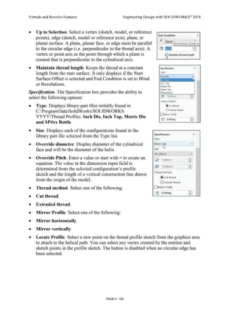
• Up to Selection. Select a vertex (sketch, model, or reference
End Condition A
points), edge ( sketch, model or reference axis), plane, or
planar surface. A plane, planar face, or edge must be parallel ~ Revol · .
Revolutions (Enter a
to the circular edge (i.e. perpendicular to the thread axis). A OJ • ~
vertex or point acts as the point through which a plane is . ~ aintain thread length
created that is perpendicular to the cylindrical axis.
• Maintain thread length. Keeps the thread at a constant Specification
length from the start surface. It only displays if the Start Type:
Surface Offset is selected and End Condition is set to Blind
or Revolutions. Inch Tap
Metric Die
Metric Tap
Specification. The Specification box provides the ability to SP4xx Bottle
select the following options: fjI 10.00mm •
•
Thread method:
• Type. Displays library part files initially found in @cut thread
C:\ProgramData\SolidWorks\SOLIDWORKS O Extrude thread
D Mirror Profile
YYYY\Thread Profiles. Inch Die, Inch Tap, Metric Die
ti 10.00deg ~
and SP4xx Bottle.
• Size. Displays each of the configurations found in the
library part file selected from the Type list. Specification A
Type:
v
• Override diameter. Display diameter of the cylindrical Metric ~ie
~
face and will be the diameter of the helix. Size
IM1 .2x0.25 vi
• Override Pitch. Enter a value or start with = to create an
I e> I J1.oomm EEi
equation. The value in the dimension input field is
I ~I 1110.oomm EEi
determined from the selected configuration's profile
Thread method:
sketch and the length of a vertical construction line drawn
@cut thread
from the origin of the model.
O Extrude thread
• Thread method. Select one of the following: D Mirror Profile
ti lo.oodeg EEi
• Cut thread.
• Extruded thread.
• Mirror Profile. Select one of the following:
• Mirror horizontally.
• Mirror vertically.
• Locate Profile. Select a new point on the thread profile sketch from the graphics area
to attach to the helical path. You can select any vertex created by the entities and
sketch points in the profile sketch. The button is disabled when no circular edge has
been selected.
PAGE 5 - 102