
Page 468 - Subyek Computer Aided Design - [David Planchard] Engineering Design with SOLIDWORKS
P. 468
Extrude and Revolve Features Engineering Design with SOLIDWORKS® 2018
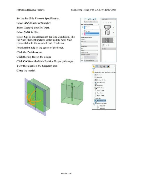
Set the Far Side Element Specification. jo~l• l• ,• I I " Near Side <
No Favorite Selected v]
Select ANSI Inch for Standard.
Near And Far Side Faces "'
G, Face<1> I : : I
Select Tapped hole for Type. T
.,,._.,,..., I
0Far Side
Select Y..-20 for Size.
I
Select Up To Next Element for End Condition. The Element Specification
Far Side Element updates to the middle Near Side Standard:
ANSI Inch v
Element due to the selected End Condition. Type:
Tapped hole v
Position the hole in the center of the block.
Size:
Far Side
~/4-20 v
Click the Positions tab. Custom sizing:
Tap Drill Diameter v
Click the top face at the origin. ~ 0.2010in
v
Click OK from the Hole Position PropertyManager. ~I~ Up To Next Element v y
View the results in the Graphics area. ~l~l~:$1~1 >
v
Close the model.
~ Advanced Hole (Default< <Defau
• [€> I History
lfi) Sensors
i,
I • [DJ Design Binder
I •
I • • fA I Annotations
I llJ Equations
'
! - - ::::o 1060 Alloy
o-
I dJ Front Plane
I"-.
'
I ' " dJ Top Plane
I "• ........... dJ Right Plane
t
I •
- ••
- • • 1... Origin
I • • • -• • f~ Boss-Extrude1]
I • • -
•
'
• ~!)rm AdvancedHole1
•
• C sketch2
•
C_ sketch3
PAGE 5 - 100