
Page 464 - Subyek Computer Aided Design - [David Planchard] Engineering Design with SOLIDWORKS
P. 464
Extrude and Revolve Features Engineering Design with SOLIDWORKS® 2018
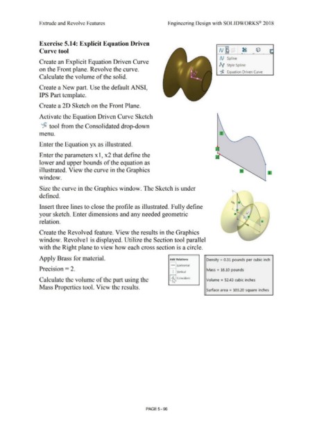
Exercise 5.14: Explicit Equation Driven
•
Curve tool N ~ ' . ~ © ~
I
i :
.
N Spline
Create an Explicit Equation Driven Curve
N Style Spline
on the Front plane. Revolve the curve.
~
Equation Driven Curve
Calculate the volume of the solid.
Create a New part. Use the default ANSI,
IPS Part template.
Create a 2D Sketch on the Front Plane.
Activate the Equation Driven Curve Sketch
~ tool from the Consolidated drop-down
menu.
Enter the Equation yx as illustrated.
Enter the parameters x 1, x2 that define the
lower and upper bounds of the equation as
illustrated. View the curve in the Graphics
window.
Size the curve in the Graphics window. The Sketch is under
defined.
<~ •
Insert three lines to close the profile as illustrated. Fully define . [
·s; ,,.
your sketch. Enter dimensions and any needed geometric a -
~
relation. '
Create the Revolved feature. View the results in the Graphics
window. Revolvel is displayed. Utilize the Section tool parallel
with the Right plane to view how each cross section is a circle.
Apply Brass for material. Add Relations Density = 031 pounds per cubic inch
- Horizontal
Precision = 2. Mass = 16.10 pounds
I :l(ertical
Calculate the volume of the part using the ~ Coincident Volume = 52.43 cubic inches
Mass Properties tool. View the results.
Surface area = 103.20 square inches
PAGE5 - 96