
Page 459 - Subyek Computer Aided Design - [David Planchard] Engineering Design with SOLIDWORKS
P. 459
Engineering Design with SOLIDWORKS® 2018 Extrude and Revolve Features
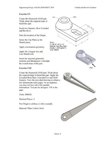
Exercise 5.9
¢16
Create the illustrated ANSI part.
Think about the required steps to
build this part.
14
Insert two features: Boss-Extrude I 12
and Revolvel. c
Note the location of the Origin.
Select the Top Plane as the
A
Sketch plane. Given: B
A = 60 B = 40 C = 8
' '
Material: Cast Alloy Steel
Apply construction geometry.
Density= .0073 g/mm"3
Units: MMGS
Apply the Tangent Arc and
Line Sketch tool.
Insert the required geometric
relations and dimensions. Calculate
the overall mass of the part. '
'
Exercise 5.10 Origin
Create the illustrated ANSI part. Think about
the required steps to build this part. Apply the
Extruded Boss/Base, Extruded Cut and Shell
features. View the provided drawing to obtain a
few dimensions (next page). As an engineer,
you may not have all of the needed
information. You are the designer. Fill in the
gaps.
Units: MMGS.
Decimal Places: 2
Part Origin is arbitrary in this example.
Material: Plain Carbon Steel.
• -
'
PAGE5 - 91