
Page 457 - Subyek Computer Aided Design - [David Planchard] Engineering Design with SOLIDWORKS
P. 457
Engineering Design with SOLIDWORKS® 2018 Extrude and Revolve Features
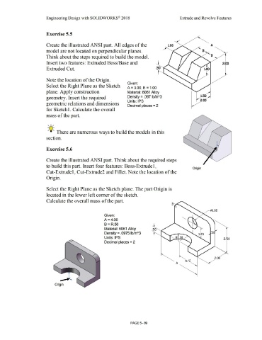
Exercise 5.5
Create the illustrated ANSI part. All edges of the
model are not located on perpendicular planes.
Think about the steps required to build the model.
Insert two features: Extruded Boss/Base and 2.00
Extruded Cut.
Note the location of the Origin.
Given:
Select the Right Plane as the Sketch
A = 3.00, B = 1.00
plane. Apply construction Material: 6061 Alloy
geometry. Insert the required Density= .097 lb/in"3 1.50
Units: IPS
geometric relations and dimensions
Decimal places = 2
for Sketch 1. Calculate the overall
mass of the part.
, ,/
-,Q-;. There are numerous ways to build the models in this
section.
Exercise 5.6
Create the illustrated ANSI part. Think about the required steps
to build this part. Insert four features: Boss-Extrude 1,
Origin
Cut-Extrude 1, Cut-Extrude2 and Fillet. Note the location of the
Origin.
Select the Right Plane as the Sketch plane. The part Origin is
located in the lower left comer of the sketch.
Calculate the overall mass of the part.
¢>1.00
Given:
A= 4.00
B = R.50
Material: 6061 Alloy
Density = .0975 lb/in"3 5
Units: IPS 2.50
Decimal places = 2
2.00
A/2
A
Origin
PAGE5 - 89