
Page 454 - Subyek Computer Aided Design - [David Planchard] Engineering Design with SOLIDWORKS
P. 454
Extrude and Revolve Features Engineering Design with SOLIDWORKS® 2018
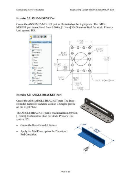
Exercise 5.2: IM15-MOUNT Part
Create the ANSI IM15-MOUNT part as illustrated on the Right plane. The IM15-
MOUNT part is machined from 0.060in, [1.5mm] 304 Stainless Steel flat stock. Primary
Unit system: IPS.
~ · ~ ~1$ 1~1 >
v
~ Exercise 5.2 IM15-MOUNT (Def
~ I History
E9-EB-EB-E9
ifl] Sensors
[ 28.70]
~ iAJ Annotations _,,-
I
<Z) l .130
~ Equations [5.54]
o- EB
i:::a AISI 304 2X ¢ .218
[P Front [61.98]
2.440
cP Top
cP Right
[ 25.40]
L Origin
l .000 [ l 2 .70 J
....- ~ Boss- Extrude1
.500
[_ Sketch1
....- ~ Cut-Extrude1
[_ Sketch2
[ 6.35]
~ g LPattern 1 __,_ 12.70
R.250
....- ~ Cut-Extrude2 .500 l2X $ .190[4.83] THRU
[_ Sketch3 [ 19.05]
.750
__ [38.10] _
1.500
Exercise 5.3: ANGLE BRACKET Part
Create the ANSI ANGLE BRACKET part. The Boss-
Extrudel feature is sketched with an L-Shaped profile
on the Right Plane. e
The ANGLE BRACKET part is machined from 0.060in,
[ 1.5mm] 304 Stainless Steel flat stock. Primary Unit
system: IPS.
• Create the Boss-Extrude I feature.
• Apply the Mid Plane option for Direction I
End Condition.
PAGE5-86