
Page 456 - Subyek Computer Aided Design - [David Planchard] Engineering Design with SOLIDWORKS
P. 456
Extrude and Revolve Features Engineering Design with SOLIDWORKS® 2018
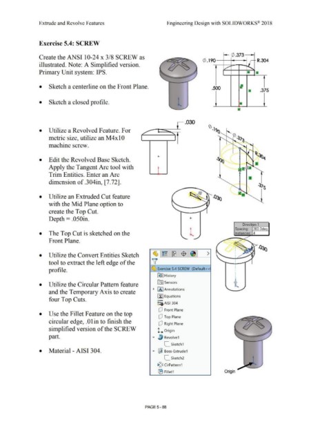
Exercise 5.4: SCREW
Create the ANSI 10-24 x 3/8 SCREW as i--- (/) .37 3 ------i
0 . 190-1-1--~ .--... R.304
illustrated. Note: A Simplified version.
Primary Unit system: IPS.
• Sketch a centerline on the Front Plane. .500
.375
l
• Sketch a closed profile.
.030
• Utilize a Revolved Feature. For I
/ '
metric size, utilize an M 4 x IO
machine screw. ... -
I ,,.
+- .~, (
• Edit the Revolved Base Sketch.
N -~
Apply the Tangent Arc tool with
,
Trim Entities. Enter an Arc
dimension of .304in, [7.72].
• Utilize an Extruded Cut feature
with the Mid Plane option to
create the Top Cut.
Depth= .050in.
Direction 1
,-----1
Spacing: 360.0de
• The Top Cut is sketched on the Instances: 4
Front Plane.
• Utilize the Convert Entities Sketch ~1~ 1~1$ 1 >
tool to extract the left edge of the v I
profile. ~ Exercise 5.4 SCREW (Default <<
~ I History
lfi] Sensors
• Utilize the Circular Pattern feature • ,....._
~ FA I Annotations
and the Temporary Axis to create
il] Equations
four Top Cuts. o-
i:::e AISI 304
r) Front Plane
• Use the Fillet Feature on the top
r) Top Plane
circular edge, . 0 I in to finish the
r) Right Plane
simplified version of the SCREW L Origin
part. Revolve1
[_ Sketch1
• Material - AISI 3 04. ... ~ Boss-Extrude1
[_ Sketch2
i:a~c:J CirPattern1
IE Fillet1 Origin
PAGE5-88