
Page 455 - Subyek Computer Aided Design - [David Planchard] Engineering Design with SOLIDWORKS
P. 455
Engineering Design with SOLIDWORKS® 2018 Extrude and Revolve Features
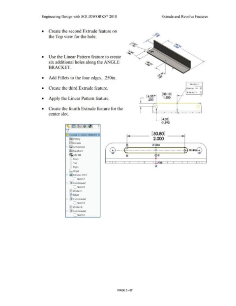
• Create the second Extrude feature on ~
the Top view for the hole. ""~,;:,~
/ ,r:
~/~ ~
"""~~
,,.;.
-...?~~
• Use the Linear Pattern feature to create
six additional holes along the ANGLE ~
~~ 0'
BRACKET.
1
117$
• Add Fillets to the four edges, .250in . •
Direction 1
• Create the third Extrude feature. Spacing: 3in ~
/ Instances: 3 ~
[ 38.10] ,...
[ 6.:;~;
• Apply the Linear Pattern feature. .250 1.500 I
/
. . '
. . '\
• Create the fourth Extrude feature for the . ·' '
center slot.
[ 4.83]
0 .190
[50 80]
~ Exercise 5.3 ANGLE BRACKET (I •
2.000
~ I History
fQJ Sensors
Q\ ;I ;(10
~ iAJ Annotations "';f:. I
G - - - - --- - - - - -·o,::.,_ =tt= tE)
il::J Equations , ;(
o- ;( .I
~:gAISI 304 ~ ('Tl
CJ Front
I I I I I I I I "'1 n I I I I I I I
CJ Top .
CJ Right
L Origin
.... ~ Extrude-Thin1
C_ Sketch1
.... [@ Cut-Extrude1
C_ Sketch2
~g LPattern1
(B Fillet1
.... [@ Cut-Extrude2
C_ Sketch3
i,',C,
c, c, LPattern2
.... [@ Cut-Extrude3
C_ Sketch4
PAGE5 - 87