
Page 458 - Subyek Computer Aided Design - [David Planchard] Engineering Design with SOLIDWORKS
P. 458
Extrude and Revolve Features Engineering Design with SOLIDWORKS® 2018
Exercise 5. 7
Rl.00
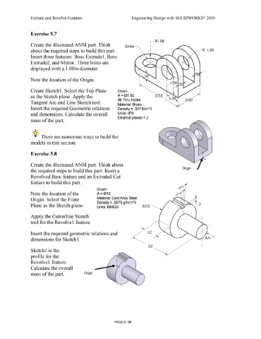
Create the illustrated ANSI part. Think 3 XIZ>A ---
about the required steps to build this part. _,,...._ R l.00
Insert three features: Boss-Extrudel, Boss-
Extrude2, and Mirror. Three holes are
displayed with a 1.00in diameter.
50
Note the location of the Origin.
Create Sketch 1. Select the Top Plane Given:
as the Sketch plane. Apply the A= 01.00 3.50
All Thru Holes 2.00
Tangent Arc and Line Sketch tool.
Material: Brass
Insert the required Geometric relations Density = .307 lb/inA3
and dimensions. Calculate the overall Units: IPS
Decimal places = 2
mass of the part.
, 1 /
;Q;. There are numerous ways to build the
models in this section.
Exercise 5.8
Create the illustrated ANSI part. Think about
Origin
the required steps to build this part. Insert a
Revolved Base feature and an Extruded Cut
feature to build this part.
Given:
Note the location of the A=012
Origin. Select the Front Material: Cast Alloy Steel
Density = .0073 g/mmA3
Plane as the Sketch plane. Units: MMGS ¢28 ----..... 2
Apply the Centerline Sketch
tool for the Revolvel feature.
Insert the required geometric relations and 12
dimensions for Sketch 1.
32
Sketchl is the
profile for the
Revolve 1 feature.
Calculate the overall
mass of the part. Origin
PAGE 5- 90