
Page 463 - Subyek Computer Aided Design - [David Planchard] Engineering Design with SOLIDWORKS
P. 463
Engineering Design with SOLIDWORKS® 2018 Extrude and Revolve Features
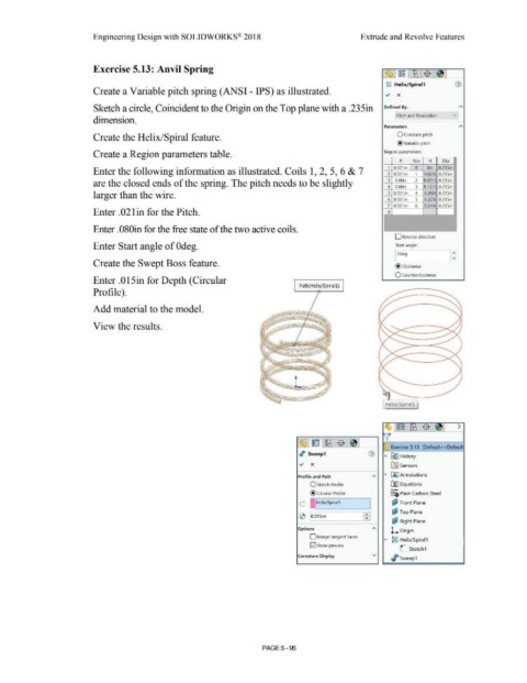
Exercise 5.13: Anvil Spring
(3, ~ - [t8 $ ~
18 Helix/ Spiral 1 G)
Create a Variable pitch spring (ANSI - IPS) as illustrated. ~ x
Sketch a circle, Coincident to the Origin on the Top plane with a .235in Defined By: A
[ Pitch and Revolution v
dimension.
Parameters A
Create the Helix/Spiral feature. O Constant pitch
@ variable pitch
Create a Region parameters table. Region parameters:
p Rev H Dia n
Oin
0.235in
Enter the following information as illustrated. Coils 1, 2, 5, 6 & 7 1 O 021 in 0 0.021 i 0.235in
2 0.021 in
1
are the closed ends of the spring. The pitch needs to be slightly 3 0.08in 2 0.0715 0.235in
4 0.08in 3 0.1515 0.235in
larger than the wire. 5 0.021 in 4 0.202i 0.235in
6 0.021 in 5 0.223i 0.235in
7 0.021 in 6 0.244i 0.235in
Enter . 021 in for the Pitch. 8
Enter .080in for the free state of the two active coils.
D Reverse direction
Enter Start angle of Odeg. Start angle:
1:
I Odeg
Create the Swept Boss feature. @ Clockwise
O Counterclockwise
Enter .015in for Depth (Circular
P ath(HeliX/Spirall )
Profile).
Add material to the model.
View the results.
Helix/Spirall
>
~ El ~ $ ~ Exercise 5.13 (Default< <Defaul
-
-
,r Sweep1 G)
~ ~ I History
~ x l'.0:] Sensors
Profile and Path A ~ IA) Annotations
O Sketch Profile ~ Equations
o-
@ Circular Profile ~::a Plain Carbon Steel
c I IHeliX/Spiral1 I Qi Front Plane
0 ;o.015in ffi: O,J Top Plane
ci.' Right Plane
Options A
L Origin
.-
D Merge tangent faces
... ~ Helix/ Spiral1
0 Show preview
L Sketch1
Curvature Display v
Jf sw eep1
PAGE5 - 95