
Page 467 - Subyek Computer Aided Design - [David Planchard] Engineering Design with SOLIDWORKS
P. 467
Engineering Design with SOLIDWORKS® 2018 Extrude and Revolve Features
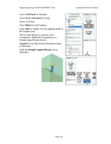
Select ANSI Inch for Standard. " Near Side <
No Favorite Selected v
Select Screw Clearances for Type.
Near And Far Side Faces
-
© Face<1>
Select Y,. for Size. I I ..
-
' l--, ii
Select Blind for End Condition. ..
Enter 1.0in for Depth. View the updated model in
Element Specification "'
the Graphics area. Standard: -~
ANSI Inch
The Far Side element is currently set to
Type:
Counterbore. Modify the Counterbore to a Screw Clearances
Straight tapped thread element. Size: Far Side
1/4 v
Expand the Far Side Element drop-down menu Fit:
Normal v
as illustrated.
Custom sizing:
[ ~'11 0.2660in
Click the Straight Tapped Thread icon as v
y
illustrated. ~IU [ Blind
0 ~.OOOOin
x
Near Side (
0
._, ....
i i
i
Far Side
0
PAGE5 - 99