
Page 466 - Subyek Computer Aided Design - [David Planchard] Engineering Design with SOLIDWORKS
P. 466
Extrude and Revolve Features Engineering Design with SOLIDWORKS® 2018
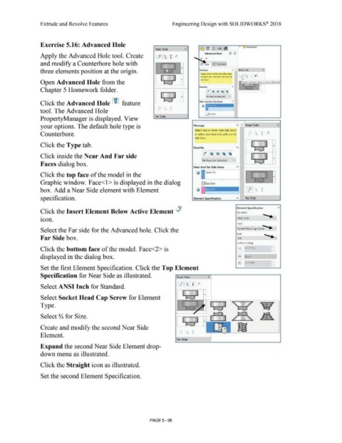
Exercise 5.16: Advanced Hole • Advanced ...
Near Side <
Apply the Advanced Hole tool. Create Advanced Hole ~ (V
and modify a Counterbore hole with u'l Type '6' Positions
three elements position at the origin. Message " A Near Side <
Selett one or mo,e neaf side fdces
I I or select one near side and one far ~ ,.A TI }' '
~id(• lor1( r.
Open Advanced Hole from the I ' Insert Element Below Active Element
.. .,. .. , ... ..1
•
Favorite "
Chapter 5 Homework folder.
No ~avorite Selected v
,
Click the Advanced Hole LID feature Near And Far Side Fa<:es A •
'i? ru 'i?
tool. The Advanced Hole .... di, i
0Far Side
PropertyManager is displayed. View Far Side
your options. The default hole type is Message A " Near Side <
Select one or more near side faces
Counterbore. or select one near side and one far -+" A 'ii' ~
'ii' ,.+.
i
side face.
Click the Type tab. I I •
Favorite A ; I
j,.f!· , ......
lo~ I • I• : ~1
I
Click inside the Near And Far side
INo Favorite Selected vi .. ....... ._.., •
•
!
Faces dialog box.
Near And Far Side Faces A
Click the top face of the model in the ~ 1 E ce<1> l •
Graphic window. Face<l> is displayed in the dialog ~ Far Side , ...... _)
box. Add a Near Side element with Element
specification. Element Specification A Far Side
,? Element Specification A
0
Click the Insert Element Below Active Element '+ Standard:
.... ._v
•
icon. ANSI Inch
Type: ....
Socket Head Cap Screw ~- vi
Select the Far side for the Advanced hole. Click the
Size: .... ._~
Far Side box. l1L4
Custom sizing:
Click the bottom face of the model. Face<2> is [ n] 0.4375in "
y
displayed in the dialog box. I Lt :;l I Blind
~ 0.2500in "
y
Set the first Element Specification. Click the Top Element •
Specification for Near Side as illustrated. Near Sid e <
Select ANSI Inch for Standard. 1 ... cr I ,..1 I 1 I.,,.
Select Socket Head Cap Screw for Element I~ •
Type. " I ~
7
....... ~-- .... ....__ .. r.
Select Y.. for Size.
I I
~ .. -.._,
I
I
Create and modify the second Near Side
v • 'f
Element.
Fa r Side
Expand the second Near Side Element drop-
down menu as illustrated.
Click the Straight icon as illustrated.
Set the second Element Specification.
PAGE5 - 98