
Page 52 - Subyek Computer Aided Design - [David Planchard] Engineering Design with SOLIDWORKS
P. 52
Overview ofSOLIDWORKS® and the User Interface Engineering Design with SOLIDWORKS® 2018
Right-click
......
. .
. .
! ••. : 9 ~ · ~lliE]Q
Right-click in the Graphics window on a model, • •
p Zoom to Fit
or in the F eatureManager on a feature or sketch
j)] Zoom to Area Feature (Extrude· Thin 1)
to display the Context-sensitive toolbar. If you Comment •
JP Zoom 1n/Out
are in the middle of a command, this toolbar Earent/Child ...
(: Rotate View
~ CQnfigure Feature
displays a list of options specifically related to + Pan X Delete ...
that command. c Roll View 00 Add to Favorites
t:g Sa:i£e Selection
Rotate About Scene Floor
Right-click an empty space in the Graphics Set Current View As ... • O Add to New Folder
I~ m feature Properties ...
window of a part or assembly, and a selection '1 View Orientation ... ~~ Ch ange Transparency
context toolbar above the shortcut menu is ~ FeatureWorks ...
Edit Scene
Open Drawing
displayed. This provides easy access to the most ~ Go To ...
Recent Commands • Create New Folder
commonly used selection tools. HideLShow Tree Items ...
Contour Select Tool
Collapse Items
Customize Menu
Consolidated toolbar '
J.1111
Similar commands are grouped together in the C1 ·1 Q, • (:) . !& Entiti
~
CommandManager. Example: Variations of the Rectangle sketch C1 Corner Rectangle
tool are grouped in a single fly-out button as illustrated. C!:1 Center Rectangle
'<), 3 Point Corner Rectangle
If you select the Consolidated toolbar button without expanding:
· <e5, 3 Point Center Rectangle
For some commands such as Sketch, the most commonly used ll Parallelogram
command is performed. This command is the first listed and the
command shown on the button.
For commands such as rectangle, where you may want to
repeatedly create the same variant of the rectangle, the last used
command is performed. This is the highlighted command when
the Consolidated toolbar is expanded.
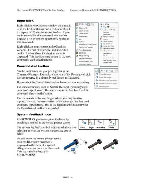
System feedback icon
SOLIDWORKS provides system feedback by
attaching a symbol to the mouse pointer cursor. ~~ hf~ ~~ ~~ 0
The system feedback symbol indicates what you are Face Edge Dimension Vertex
selecting or what the system is expecting you to
select.
As you move the mouse pointer across
your model, system feedback is
displayed in the form of a symbol,
riding next to the cursor as illustrated.
This is a valuable feature in
SOLIDWORKS.
PAGE 1 - 18