
Page 76 - Subyek Computer Aided Design - [David Planchard] Engineering Design with SOLIDWORKS
P. 76
Fundamentals of Part Modeling Engineering Design with SOLIDWORKS® 2018
Project Situation
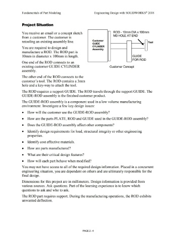
You receive an email or a concept sketch ROD - 1 Omm DIA x 1 OOmm
M3 HOLE AT END
from a customer. The customer is
-
retooling an existing assembly line. Customer Tool
GUIDE
CYLINDER
You are required to design and
Assembly
manufacture a ROD. The ROD part is
1 Omm in diameter x 1 OOmm in length. GUIDE
FOR ROD
One end of the ROD connects to an
existing customer GUIDE CYLINDER Customer Concept
assembly.
The other end of the ROD connects to the
customer's tool. The ROD contains a 3mm
hole and a key-way to attach the tool.
The ROD requires a support GUIDE. The ROD travels through the support GUIDE. The
GUIDE-ROD assembly is the finished customer product.
The GUIDE-ROD assembly is a component used in a low volume manufacturing
environment. Investigate a few key design issues:
• How will the customer use the GUIDE-ROD assembly?
• How are the parts PLATE, ROD and GUIDE used in the GUIDE-ROD assembly?
• Does the GUIDE-ROD assembly affect other components?
• Identify design requirements for load, structural integrity or other engineering
properties.
• Identify cost effective materials.
• How are parts manufactured?
• What are their critical design features?
• How will each part behave when modified?
You may not have access to all of the required design information. Placed in a concurrent
engineering situation, you are dependent on others and are ultimately responsible for the
final design.
Dimensions for this project are in millimeters. Design information is provided from
various sources. Ask questions. Part of the learning experience is to know which
questions to ask and who to ask.
The ROD part requires support. During the manufacturing operations, the ROD exhibits
unwanted deflection.
PAGE2 - 4