
Page 77 - Subyek Computer Aided Design - [David Planchard] Engineering Design with SOLIDWORKS
P. 77
Engineering Design with SOLIDWORKS® 2018 Fundamentals of Part Modeling
The engineering group calculates working
~ ~~ $~ > ~r~·~r$r~, >
loads on test samples. Material test samples v v
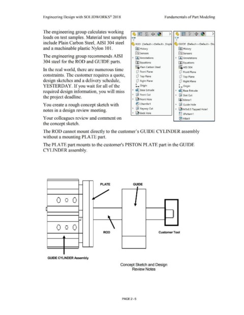
include Plain Carbon Steel, AISI 304 steel ~ ROD (Default< <Default> _Displ ~ GUIDE (Default < <Default> _Dis
and a machinable plastic Nylon 101. ~ I History [€> I History
~ Sensors ~ Sensors
The engineering group recommends AISI
• 1/l I Annotations ~ [A I Annotations
304 steel for the ROD and GUIDE parts. [fl Equations ~ Equations
o- o-
~:a Plain Carbon Steel ~:,c; AISI 304
In the real world, there are numerous time
[!] Front Plane [!] Front Plane
constraints. The customer requires a quote, [!] Top Plane [!] Top Plane
design sketches and a delivery schedule, [!] Right Plane [!] Right Plane
YESTERDAY. If you wait for all of the L Origin L Origin
required design information, you will miss • ~ Base Extrude • ~ Base Extrude
• ~ Front Cut ~ ~ Slot Cut
the project deadline.
• ~ Front Hole Caliil M irror1
You create a rough concept sketch with i:l'.J Chamfer1 • ~ Guide Hole
notes in a design review meeting. • ~ Keyway Cut ~ ~ M3x0.5 Tapped Hole1
• ~ Back Hole gg LPattern1
Your colleagues review and comment on (B Fillet 1
the concept sketch.
The ROD cannot mount directly to the customer's GUIDE CYLINDER assembly
without a mounting PLATE part.
The PLATE part mounts to the customer's PISTON PLATE part in the GUIDE
CYLINDER assembly.
PLATE GUIDE
0 0 0
-
0 0 0
ROD Customer Too I
GUIDE CYLINDER Assembly
Concept Sketch and Design
Review Notes
PAGE2 - 5