Page 71 - Subyek Computer Aided Design - [David Planchard] Engineering Design with SOLIDWORKS
P. 71

Engineering Design with SOLIDWORKS® 2018                                                                                                     Overview of SOLID WORKS® and the User Interface


                                                                        Templates are part, drawing and assembly documents which include user-defined


                                                                       parameters. Open a new part, drawing or assembly. Select a template for the new


                                                                        document.


                                                                        •  Parts. The Parts default template is located in the


                                                                                    C :\ProgramData \SolidWorks\ \SOLIDWORKS 2018\templates\Part.prtdot folder.


                                                                        •  Assemblies. The Assemblies default template is located in the


                                                                                    C: \Pro gramData \SolidW orks \\SO LID WORKS 2018\temp lat es \Assemb 1 y. asmdot


                                                                                   folder.


                                                                        •  Drawings. The Drawings default template is located in the


                                                                                    C:\ProgramData\SolidWorks\\SOLIDWORKS 2018\templates\Drawing.drwdot


                                                                                    folder.


                                                                          ,    1 /


                                                                          -;Q;:,  For commercial users, SOLIDWORKS Model Based


                                                                       Definition (MBD) is a separate application. For education


                                                                       users, SOLIDWORKS MBD is included in the


                                                                        SOLIDWORKS Education Edition as an Add In.


                                                                        In Project 2, obtain the working familiarity of the


                                                                        following SOLIDWORKS sketch and feature tools:


                                                                       Line, Circle, Centerpoint Straight Slot, Smart


                                                                       Dimension, Extruded Boss/Base,  Extruded Cut and


                                                                       Linear Pattern.


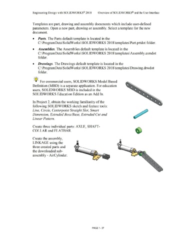
                                                                        Create three individual parts: AXLE, SHAFT-


                                                                        COLLAR and FLATBAR.


                                                                        Create the assembly,


                                                                        LINKAGE using the


                                                                        three created parts and


                                                                        the downloaded sub-


                                                                        assembly - AirCylinder.


                                                                                                                                                                                                        PAGE 1 -37
   66   67   68   69   70   71   72   73   74   75   76