
Page 68 - Subyek Computer Aided Design - [David Planchard] Engineering Design with SOLIDWORKS
P. 68
Overview ofSOLIDWORKS® and the User Interface Engineering Design with SOLIDWORKS® 2018
3D Views tab
~
~
(I
\I!
Ei Iii, i;· " Ill - A ~ v" I" A Jl' 'f' (' 1' ::i Iii ill U • ' el '°"" """"'• P<iU"' ~sr.-,
"'-~ ~ '""' ..-.~c-.~ ~
SOLIDWORKS MBD (Model ~ ,__~ o;- "*'- ·- °"""'w", ~ •~....,,,.. *.,.. ~ .... "'*" c:.- ~ ~ ~ c,,,.,-oe-
...,_,.~,...,,.
r...,.,, .... .......
l!l .... v.. """'*"""" v.. -.-..,,.,_ ...,_., .... ll)r\'f" .tai--,.li, ,..,,_
Based Definition) lets you create
models without the need for drawings giving you an Capture 30 View
Sort order:
integrated manufacturing. MBD helps companies define, History
organize, and publish 30 product and manufacturing I .Jpd t<> Pr@v1ews '
information (PMI), including 30 model data in industry ~ ~(~
standard file formats.
Create 30 drawing views of your parts and assemblies that
contain the model settings needed for review and ~
I . . Model l 30 Vie NS I Motion Study 1J
manufacturing. This lets users navigate back to those "OLIDWORKS Premium 2017 x64 Ehd'ion
settings as they evaluate the design.
~ w I
.; Assembly
Use the tools in the SOLIDWORKS MBD '
\Y.;
> Layout
CommandManager to set up your model with selected - .; Sketch
configurations, including explodes and abbreviated views, • .; Evaluate
annotations, display states, zoom level, view orientation Render Tools
0 SOUDWORKS Add-Ins
and section views. Capture those settings so that you and
SOUDWORKS MBD
other users can return to them at any time using the 30
0 Use Large Buttons with Text
view palette.
Customize CommandManager ...
To access the 30 View palette, click the 3DViews tab at the
bottom of the SOLIDWORKS window or the
SOLIDWORKS MBD tab in the CommandManager. The
Capture 30 View button opens the Capture 30 View
PropertyManager, where you specify the 30 view name,
and the configuration, display state and annotation view to
capture. See SOLIDWORKS help for additional
information.
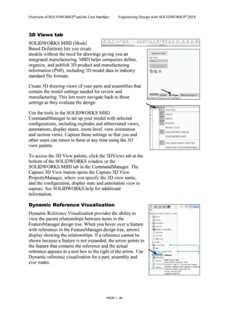
Dynamic Reference Visualization
~ [ ia~r llS' I$ . fl > c, e s, LPatternl
v'
Dynamic Reference Visualization provides the ability to ~ Bracket (Default< <Default> _Display
• ~History
view the parent relationships between items in the lfl] Sensors
F eatureManager design tree. When you hover over a feature • IA) Annotations
[fJ Equations
with references in the F eatureManager design tree, arrows o-
~=i Material <not specified>
Q Front Plane
display showing the relationships. If a reference cannot be Q Top Plane
Q Right Plane
shown because a feature is not expanded, the arrow points to t.. Origin
the feature that contains the reference and the actual • ~ Extrude·Thin1
(B Filletl
reference appears in a text box to the right of the arrow. Use • 05.0 (5) Diameter Hole1
s, ~-
c,c, atternl LPattern1
Dynamic reference visualization for a part, assembly and • ~0 .O(lO)D ______ _
e,c, LP 2 Pattern type: Linear
ever mates. c,c, attem Seeds: 05.0 (5) Diameter Holel
• ~ Cut-Extrude' Direction 1: Edge<l >, Spacing and instances
~~ LPattem3 Direction1 settings: 20mm spacing, 2 instance
Direction2: Pattern Seed only' No
Instances skipped? No
Instances varied? No
PAGE 1 - 34