
Page 247 - Estimators Piping Man Hour Manual
P. 247
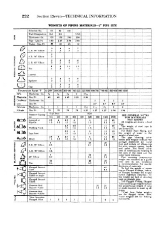
222     Section Eleven—TECHNICAL   INFORMATION


             Schedule  No.  40  80  160                        4    1    '   J
             Wall Designation  Std.  xs  xxs          1    1   1         t
                                                      i ...
      s      Thickness — In.  .133  .179  .250  .358  .  .^_  t
             Pipe— Lbe/Ft  1.68  2.17  2.84  366
                                                              .  4-
             Water— Lbs/ Ft  .37  31  23  12
                         .3  .4   .6                                :    !
                                   —                                t    '   1
             L.R.  90° Elbow  .3  .3  .3  I
                         2
             8.R. 90° Klbow  .2
      o
                         .2  .3   .4  .4
             L.R.  45" Klbow  .2  .2  .2                       L _ i  __! ._ .
                         .8  .9   1.1  1.3                 i   I
             Tee         .4  .4   4    4
             1 aWral
                         3   .4   4
             (Reducer    ,2  .2   .2   .2
                         .2  .3   4   .4
             Cap         3   .3   .3  .3
        Temperature Range  'F  to  260°  100-360 360-440 440-525 525-600 600-700 700-800 800-900 900-1000  j
             Thickness  In  H  H  1H  2   I's-it
      Z  Magnesia  Lbs/ Ft  .65  65  1  45  2  25  220  — — -
      2  (Jombma- Thickness  In                 2  _____  2   2              ~1
      ^  lion  Lbs 'Ft                         3.7       37   3.7
       Calcium  Thickness  In  1  1  1  1  IM  m    1 ?4  j  2  2
       Kihcate  I bs  I- 1  .75  .75  .75  .75  1.27  1  27  1.27  1  1  94  1 94
              Pressure  Rating  Cast  Iron  Steel             SEE GENERAL  NOTES
              psi       125  250  150  300  400  600  900  1500  2500  FOR  MATERIALS
                                                                    SHOWTV
                                                                 NOT
                                             5
                                     4
              Strewed or  2.5  1.5  2.5  1.5  1.5    1.5  1.5  All  »weights are  shown in  tvjid
                                                         15
                             4
                                                     12
                        1.5
             Shp-On
                                1.5
      FLANGES  Welding Neck     2.3  4.8     1.5     1.5  1.5  type  oi  steel  pn>e  »a
                                                         15
                                                     11
                                             7
                                                              The weight
                                    1.5
                                1.5
                                                            per bnf ar foot
                                2.5  4       5       12  15   For Boiler  Feed  Piping,  add
              Lap Joint         1.5  1.5    1.5      1.5  1.5  the  w Jight  of  water  to  the
                                                            weight of  steel pipe
                        2.5  4  25   5       5       12  15   The  pipe  covering  thick-
              Blind     1.5  1.5  1.5  1.5   1.5     1.5  1,5  nesses and  weights  indicate the
                         6         !         15      28     averagf  conditions  per  linear
                                                                  include
                                                               an d
              8  R  90° Klbow  3.6          3.7      3.8    foot wirB|  cement,  all  allowances
                                                                          b^in is
                                                            for
                                                                      canvas,
      n   a   L R  90° Klbow  3.8                           and  of combination hited  thiik- >s
                                                                   The
                         S
                                                               piint
                                                                        covenriR
                                                            ness
      1  &    45° Klhow  3.2                3.4      3.6    the Pipe  covering  inner  anrt  the
                                                               su •a
                                                                  of
                                                                   the
                                                            outer Ittyer thickness
                                             14
                         5
                                                     26
                                                                       temiieratuw
                        11                   20      39     ranges are  intended  as a  guide
                                                            only
                                                                t nd
                                                                        constitute
                                                                     not
                                                                   do
              Tee       5.4    1            5.6      5.7    a  recommendation  for  spt-< me
                                                                ss of materials
              Flanged  Bonnet                        67       To ft nd  the  weight  of cover-
              Gate                                   4.3    ing on Flanged  Fittings, \ gives,
                                       __
              Flanged Bonnet                   i            or  Flii ges,  multiply  tht  weight
                                                                           l
                                                                            by
                                                            factor (lightface
                                                                      subscript
              Globe or
                   Angle
      i  o    Flanged  Bonnet  1       ,               1    the  we ght  per  foot  of  covering
                                                            u>>ed
                                                               or straight pipe
              Check
                                                              •All Flanged
                                                                     w eights i ru ] ude
                                                            \alveand Flange Fitting,  Flanged
              Pressure Seal                      31  31     the proportioiia! weight of  holts
              Bonnet  -Gate                      1.7  0.9   or stud s required  to  make up all
                                                            joints
              Pressure  Sc al                                 **Cast  Iron  Valve  »eight«i
              Bonnet— Globe
                                                            are  fo•  flanged  valves  Steel
      3       'One  Complete  1  2  i  2     2       6   6  \ alve  weights  are  for  welding
                                                            end valves.
              Flanged
                  Joint