
Page 252 - Estimators Piping Man Hour Manual
P. 252
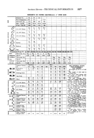
Section Eleven—TECHNICAL INFORMATION          227

                       WEIGHTS  OF  PIPING  MATERIALS—3"  PIPE  SIZE
            Schedule  No.  40  80  U»0                    I                 -1
                            xs
     s      Wall  Designation  Std.  .300  437  XX  s  _  _ |
                       .216
                                     iiOO
            Thickness — -In.
            Pipe— Lbs/Ft  7.58  10.25  1432  18.58  -
                                                       —             _-
            Water— Lbs/Ft  3.20  2.86  2  35  1.80
                        46  6 1  8.4  10.7
             L.R.  90" Klbow  .8  .8  .8
                        3    4
            S.R.  90° Elbow  .5  .5                            [
                        2.4  32  4.4  5.4
     £  LL)  L.R.  45° Klbow  .3  .3  .3  .3
                        7.4  9.5  12 2  14.8
            Tee         .8   .8  .8   .8
                        17  24
             Lateral    1.8  1.8
                        2.2  2 9  3.7  4.7
            Reducer     .3   .3  .3   .3
                        1.4  1.8  3.5  3.7
            Cap         .5   .5  5    .5
       T«?mp«rature Range "F  to 260°  260-360 360-440 440-525 525-600 600-700 700-800 800-90C 90O-IOOO]  1
      85%    Thickness — In  1!^  Ufts  l'i  2  25*2
                                                                      -I
     Z  Magnesia  Lbs/Ft  1.55  1 55  265  3.95  425                  1
     p  Combina- Thickness — In.              3Ks  3!4  3%   3%       !
     g  tion  Lbs/Ft                          8.3  8 3  107  10 7       r:z:
      Calcium  Thickness— In.  I  1  1  Ha  1H  2  2'u  2>' S  3  1   '     ~
      Silicate  Lbs/Ft  1.28  1 28  1 28  2.09  209  298  398  398  5  11  !
                        Cas>t Iruif        Steel
             Pressure Rating                                 SEE  GENERAL  NOTES
             p&i       125  250  150  300  400  600  900  1500  2500  FOR  MATERIALS
             Screw ed  or  9    10  17      20  38  61  101     NOT  SHOWN
                                                             All weights are shown
             Slip-On   1.5  t.5  1.5  1  5  1,5  1.5  1.5  1.5  type     m bold
      FLANGES  Welding Neck     10  1 17 5  24  1.5  1.5  101  per In ear  foot.  of  steel  pipe  is
                                                35
                                                    54
                                                             The weight
                                                        1.5
                                1.5
                                            1.5
                                10  17      21  38  62  100  For Boiler  Peed  Piping,  add
             Lap Joint          1.5  1.5    1.5  1.5  1  5  1.5  the  M•eight  of  water  to  the
                                                            Weigh of  ->teel pipe,
                        10  19  11  20      24  39  61  104  The  pipe  covering  thic.k-
             Blind     1.5  I  5  1.5  1.5  1.5  1.5  1.5  1.5  nesses and  weights  indicate  the
     <ti  x-f          26  46   32  53      67  98  150     averaee  conditions  per  linear
     Q   /  j!  S.R,  90" Elbow  3.9  4  3.9  4  4,1  4.3  4.6  foot wire, cement, canvas,  band*
                                                                       allowances
                                                                 include
                                                                     all
                                                              anil
                                                            for
                       30  50   40  63                      .uid  iMint.  The  listed  thick-
             L.R. 90° Elbow  43  4.3  4.3  4.3                 '  combination covering  is
                                                            the  si m  of  the  inner  and  the
                       22  41   28  46      60  93  135     outer ayer thickness,
             45" Elbow  3,5  3.6  3.5  3.6  3.8  3.9  4      Pipt  covering  temperature
                                                            ranges are  intended  as  a  j;uide
                       39  67   52  81    ^102  151  238    only  and  do  not  constitute
             Tee       5.9  6  5.9  6       6.2  6.5  6.9   a  rect mmendation  for  specific
      wQ     Flanged Bonnet  66  112  77 4  119  153  225  338  thickr ess of materials.  of  cover-
                                                                 the
                                                                    weight
                                                             To ind
                                            4.8
                                                    5.3
                                                4.9
                           7.4
                                   4.4
             Gate
                                                                    Fittings, Valves,
                                                            ing on Flanged
                                                            or  Flanges,  multiply  the  weight
                                80
                 Bonnet
                       56
             Flanged or Angle  7.2  121  4 2  102  132  242  341  factor (lightface  subscript}  by
                           7.6
                                            4.8
                                   4.6
                                                4.9
                                                    5.3
             Globe
     !   o   Flanged  Bonnet  7.2  7.6  4.2  101  4.8  4.9  233  the *A11 Flanged  foot  of  covering
                                                                  per
                                                              w( ight
                                                            used on straight pipe,
                                            91
                           100
                                                146
                       46
                                51
                                                                         Flanged
                                                                    Fitting,
             Check
                                   4.6
                                                    5.3
                                                                     weight
             Pressure Seal                      140  140    Valve ind Flange weights include
                                                                         of bolts
                                                            the proportional
             Bonnet — Gate                      2.5  2.5    or  stu< '.a  required  to  make up  ai!
                                                            joints.
       NO    Pressure Seal                      160  260    are **("ast  flanged  Valve  weights
                                                                 Iron
             Bonnet- — C lobe
                                                2,5
                                                    2.5
                                                              f< T
                                                                          Steel
                                                                     valves.
     8       *One Complete                                  Valve weights  are  for  nclJmg
     i       Flanged Joint.  1.5  6  1.5  7.5  8  12.5  25  end vaIvea.