Page 255 - Estimators Piping Man Hour Manual
P. 255

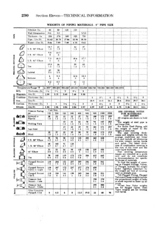
230     Section Eleven—TECHNICAL    INFORMATION

                        WEIGHTS  OF PIPING  MATERIALS  5"  PIPE  SIZE
              Schedule  No.  40  80  120  IhO
              Wall Designation  Std.  xs  \\S     [         i
      £       Thickness—In.  .258  .375  .,500  »>25  750  T  "  t   -   t
      &                                                       __
              Pipe— Lbs/Ft  14  62  20 78  2704  *2  %  18  55  ~ J  f
              Water— I, hs/ Ft  8 66  7.89  7 09  6 «  5.62  t
         0    L.K. 90° Klbow  14.7  1.8  1.3  37
                                       32
                              21
                         1.3
                                           1.3
                         9.8  13.7                     [•            |
              S.R,,  90°  Elbow  .8  .8                i             i  _ _
      Q
                         7.3  10  2   15.6  17.7           T
              L.R. 45° Klbow  .5  .5   .5
                                                                    f    .___
                         19 8  26      39  43
              Tee        1.2  1.2     1.2  1.2
                         49   70
              Lateral    2.5  2.5
      '/TV,              6   8.3      12.4  14 2
        C-4—J  Reducer   .4   .4       .4  .4                        1
                         4 2  5.7      11  11
              Cap        .7   .7       .7  .7                        1
        Temperature flange  °F  to  260° 260-3,60 360-440 440-525 525-600 600-700 700-800 1 800-900 j 900-1000
                                                       .                .
       85%    Thickness— In.  I'-i  Hi  2  2 ''2  3
      tj  Magnesia  Lbs/Ft  2.50  3.75  5.60  7.40  9 30  I          7"
      a  Combina- Thickness — In.               3   31   4    4»i  i  5  f  *' 4  6
                                                      -  i
      >  tkra  Lbs/Ft                          10.9  13.31  16.1  20.6  25.6  29.7  34.1
      8  Calcium  Thickness — In.  1  1 I~~TH  l'/2  2  2  21  s TL-JL  3  3?* _J_  4'i
       Silicate  Lbs/Ft  1.84  1.84  2.84  2.84  3.97  3.97  5.37  I  6.75  6.75  8.26  10.3  12.1
                         Cost  Iron         Steel
              Pressure Rating                                 SEE  GENERAL NOTES
              psi       125  250  150  300  400  600  900  1500  2500  FOR  MATERIALS
              Screwed  or  20  32  18  32  37  73  100  172  259  NOT  SHOWN
      gfcta*  Slip-On   1.5  1.5  1.5  1.5  1.5  1.5  1.5  1.5  1.5  All weights are  shown in bold
                                 18  31  42  70  94  145  263  'The weight  of  steel  pipe  is
              Welding Neck       1.5  1.5  1.5  1.5  1.5  1.5  1.5  per lir ear foot.
                                                                       Piping,
                                             75
      "tod    Lap Joint          1.5  1.5  39  1.5  101  171  257  the For Boiler  of Feed water  to  add
                                     33
                                 19
                                                                            the
                                                               *'eight
                                         1.5
                                                         1.5
                                                 1.5
                                                     1.5
                                                             weigh , of steel pipe,
                         23  37  23  39  50  78  104  172  272  The  pipe  covering  thiek-
       ^S£p2O  Blind    1.5  1.5  1.5  1.5  1.5  1.5  1.5  1.5  1.5  nesses and  weights indicate  the
      i   j   S.R.  90° Elbow  4 3  4.3  4 3  113  123  205  268  43*  averaj e  conditions canvas,  linear
                                                                        per
                         58
                                 80
                             94
                                                                  include all
                                                               and
                                                                        allowances
                                                             foot
                                             4.7
                                                     5.2
                                                 4.8
                                         4.5
                                     4 3
                                                                  cement,
                                                               wire,
                                                             for
                                                                           bands
      I  ^    L.R. 90° FJbow  4.7  4.7  4.7  128             and  aamt.  The  listed  thiek-
                         68
                             105
                                 91
                                                             ness of
                                                                 combination
                                                                        covering is
                                     4.7
                                                               siim
      | £     45° Elbow  3.8  83  3.8  3.8  .  123  180  239  350  the Pip<s  covering inner  and  the
                                                                  of
                                                                    the
                                                             outer ayer thickness.
                                     98
                                 66
                         51
                                         4
                                                 4.3
                                                     4.5
                             3.8
                                                                       temperature
                                             4,2
      3                  90  145  119  172  179  304  415  665  1  ranges are  intended  as  a  guide
         Q    Tee       6.4  6.5  6.4  6,4  6.8  7.2  7.8    only and  do  not  for constitute
                                                                          spec-ifie
                                                             a
                                                              rec<mimendation
       i<0    Gate      138  264  151  257  309  386  508  841  J  thirkness of materials. the of  weight
              Flanged Bonnet
                                                              To find
                                                                   the
                                                                     weight
                                                                           cover-
                        7.3
                                                 5.8
                             7,9
                                 43
                                                     6.3
                                         5.3
                                     4,9
                                             5.5
                                                             ing on Flanged
                                                                     Fittings, Valves,
                                                              Flanges,
                                                                   multiply
                                                             or
              Flanged Bonnet
                                         5.3
                                 4.6
                             8
                                             5.5
                        7.6
      a wO    Globe  01  Angle  138  247  172  237  277  274  658  factor (lightfaoe foot subscript)  by
                                                 5.8
                                     5
                                                                         covering
                                                                   per
                                                                        of
                                                               w ?ight
                                                             the
                                                             used on straight pipe.
              Flanged Bonnet
      f   0   Check     118  210  141  198  249  244  326  531  Valveand Flange weights include
                                                                     Fitting, Flanged
                                                              *A1 Flanged
                        7.6
                                         5.3
                             8
                                             5.5
                                                 5-8
                                                     6.3
                                     5
                                 4.6
              Pressure Seal                      350  378    the  proportional weight of bolts
              Bonnet-  Gate                      3.1  3.4    or stu4s required to make up all
                                                             joints
              Pressure Seal                      395  500     "Cast  Iron  Valve  weights
              Bonnet  Globe                      3.1  3.4    are  f ar  flanged  valves.  Steel
                                                             Valve weights
      i       'One Complete  6  6.5  6  8  12.5  19.5  33  60  98  end viilve«.  are  lot  welding
              Flanged Joint
   250   251   252   253   254   255   256   257   258   259   260