Page 251 - Estimators Piping Man Hour Manual
P. 251

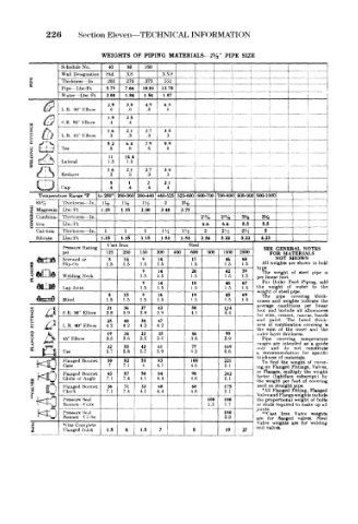
226     Section Eleven—-TECHNICAL   INFORMATION

                       WEIGHTS  OF  PIPING  MATERIALS-  2l/ 2"  PIPE  SIZE
              S< hedule  No.  40  80  160     I   I    I   ,
              Wall  OfMgnation  Std.  xs  xxs  '  !  [          i   i
      H                                       r  —\- -  *-  -  1 -~r  -  ,
      fc      Ihxkness  In  .203  .276  .375  .552
      £
              Pipe  LWH  5.79  7.66  10.01  13.70                   1
              Water  Lbs  Ft  208  1.84  1  54  1.07  1  T  !   f
                         2.9  3.8  4.9  6.5
              L  R .90°  Elbow  .6  .6  .6  .6                  >
                                                                  " f
                         1.9  2 5                               1
              S.R. 90°  Elbow  .4  A
      Q                                       1   *
                         1.6  2.1  2.7  3.5
              L.R. 45° Elbow  .3  .3  .3  .3
                                                       !        i
                         5.2  64  7.9  9.9
              Tee         8   .8  .8   .8              j            j
                         11  14.4             j        i   f        t
      le£)    Lateral    1.5  1.5
      Vis     Reducer    16   2 1  2.7  3.4        1  _.
                                  .3
                              .3
                         .3
                                       .3
          L—P
        8
                          8   1    2   2.1        1             i
              Cap         4   .4  .4   .4
        Temperature Range °F  to 260° 260-360 360-440 440-525 525-600  600-700 700-800 800-900 900-1000  1  i
        ot> ,0  Thickness  —In m z  IHi  \Yt  2  2%                  T
      Z  Magnesia  Lbs  Ft  1.35  1.35  2.30  3.40  3.75
      p  Conibina- Thicknoss  -In              2%   2%   3%   m      1_  L -
      §  tion  Lbvft                            6.6  6.6  8.5  8.5
        Call mm.  Thickm-sh— In  1  1  1  m  Hi  2  2  2 t~2H  3     _.      .
                                                     ''  +__             1
        Silicate  Lbs/ Ft  1.15  1.15  1.15  1.53  1.53  2.34  3.22  |  3.22  4.23
                         fast  Iron          Steel
              Pressure Rating                                  SEE  GENERAL  NOTES
              psi        125  250  150  300  400  600  900  1500  2500  FOR  MATERIALS
                                                                     SHOWN
                                                                 NOT
                                 9
                                             17
              Screwed  or  1.5  1.5  1.5  14  1.5    1.5  68  All  weights are shown  in bok
                         8
                                                     46
                             14
                                                         1.5
              Slip-On
                                     1.5
       FLANGES  Welding Ne<k     1.5  1.5    1.5     1 5  59  type  weight  of  ate* 1  pipe  u>
                                     14
                                             20
                                                     42
                                 9
                                                              The
                                                         1.5
                                                                   foot
                                                             per linear
                                 9   14      18      46  67   For  Boiler  Feed  Piping,  ark
              1 ap  Joint        1.5  1.5    1.5     1.5  1.5  the  weight  of  water  to  the
                                                             weight  of steel pipe
                         8   15  9   16      19      45  69   The  pipe  covering  thick-
              Bhnd       1.5  1 5  1.5  1.5  1.5     1.5  1.5  nesses  and  weights indicate  th«
                                                             a\erage  conditions all  per  lineal
                                             50
                         21
                                     42
                                 27
                                                     LM
                             36
            *i°A
       FITTINGS  W  S L R R  90° Elbow  3.8  39  3.8  3.9  4.1  4.4  for  wire, combination listed  thick- it
                                                                and
                                                             foot
                                                                  include
                                                                        allowances
                                                                       canvas.,
                                                                           bauda
                                                                  cement,
                                                                    The
                                                             and
                                                                paint
                                 30
                                     47
                         25
                             40
                                                                of
                                                                        cohering
                                                             ness
                                 4,2
                         4 2
                 90° Elbow
                                     4.2
                             4.2
                                                                          and
                                                               sum
                                                                    the
                                                                      inner
                                                                            the
                                                                  of
       FLANGED  Hft>^t\  AH** -Hf  Tee  3.5  34  3.5  3.6  3.8  39  the Fipe and covering not  temperature
                                                     99
                                                             outer laver
                         19
                                             46
                                     35
                                 22
                                                                   thickness
                             3.6
              45° Klbow
                                                             ranges
                                                                 are
                                                                        as
                                                                          a
                                                                   intended
                                                                           guid«
                                             77
                             55
                                 42
                                     61
                         32
                                                     169
                                                                         constitute
                                                                   do
                                                             onl>
                                     5.9
                                             (i,2
                                                     6.6
                         5.7
                             5.8
                                 5.7
                                                              recommenddtiun
                                                                          speufir
                                                                   the
                                                              To
                                                                           cover-
        KO    Hanged  Bonnet  50 7  ~ 82 1  53 4  83  108  221  a thickness of materials for of Valves
                                                                     weight
                                                                find
                                                     5.1
              Gate
                                     4.1
                                             4.6
                                                             ing on
                                                                 Flanged Fitting,
              I landed  Bonnet  43  87  50  84  98   242     or  Flanges,  multiply  thf  wt'ighl
                                                                       subscript)
                                                                             bj
                                                             factor
                                                                 (lightface
      n&Q     Globe or  Angle  7  1  7.4  4.1  4.4  4.6  5.1  the  weight  per  foot  of  covering
              Hanged  Bonnet  36  71  32  68  68     175     used on straight pipe
                                                              * \11 Flanged
                                                                          Flanged
                                                                     Ftttme,
          0 <  he<!<     7  1  7.4  4.1  4.4  _  4.6  5.1    Valve and Flange weights include
              1'ressure Sea!                     106  100    the  proportional weight  of boite
      '"MtO   Bonnet  < .ate  r  i               2.3  1.7    joints.
                                                             or studs required to make up ai
        NO    Pressure  Sf.»l                        180     are "Cast  flanged Valve  weights
                                                                   Iron
              Bonnet
                   ( ! il*
                                                     2.3
                                                                       valves,
                                                                            fneei
                                                                for
       s      •One Complete  i  ,                            Valve  weight*  are  for  welding
      »       J Unged Joint  1 5  6  1.5  j  7           27  end  valves.
                                              * j  [,. *'
   246   247   248   249   250   251   252   253   254   255   256