
Page 256 - Estimators Piping Man Hour Manual
P. 256
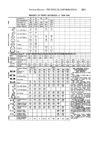
Section Eleven—TECHNICAL INFORMATION 231
WEIGHTS OF PIPING MATERIALS—«" PIPE SIZE
Schedule No. 40 80 120 160 i
Wall Designation Std. xs xxs
S Thickness— In, .280 .432 .562 .718 .864
E _ L _
Pipe— Lbs/Ft 18.97 28.57 36.39 45.3 53.2 1
Water— Lbs/ Ft 12.51 11.29 10.30 9.2 8.2
23 34 53 62
L.K. 90° Elbow 1.5 1.5 1.5 1.5
, '& S.R. 90° Elbow 15.2 23 1
1
11.3 16.7 26 30 I ! T
L.R. 45° Elbow .6 .6 .6 .6 i 1 [
42
0 E..J- _1 Tee 29.3 1.4 60 68
1.4
1.4
1.4
79
I e^ Lateral 2.9 101 j
29
/A 8.7 126 18.8 21 j
1 — i — 5 Reducer .5 .5 .5 .5
6.4 9.2 17.5 17.5
Cap .9 .9 .9 .9
Temperatiire Range °F to 260° 260-360 360-44C 440-525 S26-600 600-700 *W-800 800-900 900-100> A
85% Thickness — In. 1H w% 2 Wt 3 i _4~ .
g Magnesia Lba/Ft 2.90 4.15 6.40 8.40 10.0 .-Hi
5 Combina- Thickness — -In . 3 3^ 4 4H 5 5H 6
ft tion Lbs/Ft 12.3 14.9 18.2 24.2 28.2 32.6 37.4
Calcium Thiekness — In . 1H 1« 1H Ik 2 2 24 3 jj 3H 4 *H
Silicate Lbs/Ft 3.13 3.13 3.13 3.13 4.54 4.54 5.92 7.42 7.42 9.47 11.2 13.1
Caat Iron Steel
Pressure Rating SEE GENERAL NOTES
psi 125 250 150 300 400 600 900 1500 2500 FOR MATERIALS
NOT
SHOWN
,
iSorewed or 25 » 1.5 45 1.5 95 128 202 395 All weighta are shown in bold
22
54
FLANGES Welding Neck 1.5 42 56 85 116 176 402 type. weight of ateel pipe is
1.5
1.5
1.5
Slip-On
1.5
1.5
1.5
22
The
1.5
1.5
1.5
1.5
1.5
1.5
per linear
foot.
24 47 56 98 131 213 393 For Boiler Feed Piping, add
Lap Joint 1.5 1.5 1.5 1.5 1.5 1.5 1.5 the weight of water to the
weight of steel pipe.
28 51 29 56 71 101 133 197 417 The pipe covering thick-
Blind 1.5 1.5 1.5 1.5 1.5 1.5 1.5 1.5 1.5 nesses and weight* indicate the
74 125 90 147 184 275 375 566 average conditions all per linear
and
include
foot
allowance*
S.R. 90° Elbow 4.3 4.4 4.3 4.4 4,6 4.8 5 5.3
bands
for wire : cement, canvas, thick-
The
paint.
listed
and
91
1 & L.R. 90° Elbow 4.9 145 126 182 ness of combination covering is
4.9
4.9
4.9
the sum of the inner and the
66 115 82 132 149 240 320 476 outer layer thickness.
§ A,
» I T> 45" Elbow 3.8 3.9 3.8 3.9 4.1 4.3 4.3 4.6 Pipe covering temperature
Z «">*
1 114 195 149 217 279 400 565 839 ranges are intended as a guide
Q Tee 6.5 6.6 6.5 6.6 6.9 7.2 7.5 8 only recommendation not for constitute
and
do
specific
a
thickness of material*.
Flanged Bonnet 172 359 210 367 409 553 784 1227 To find the weight of cover-
K3 Gate 7.3 8 4.3 5 5.S 5.8 6 6.6 ing on Flanged Fittings, Valves,
Flanges,
or
p^O Globe or Angle 184 345 238 333 366 465 844 factor weight per foot subscript) by
multiply
the wekht
Flanged Bonnet
(lightface
8.2
5.4
7.8
4.8
5.2
5.8
6
covering
of
the
0 Check Bonnet 154 286 176 272 341 335 459 877 used on straight j)ip«. flanged
Flanged
Fitting,
"All Flanged
5.4
5.8
6
8.2
4.8
5.2
r 7.8 6.5 Valve and Flange weights include
f^0 Pressure Seal 540 600 the proportional weight of bolts
or studs required to make up all
Bonnet — Gate
3.8
3.5
K) Pnssuure Seal 600 709 joints. for flanged Valve weights
"Cast
Iron
Bonnet — Globe
3.8
3.5
Steel
valves.
are
i Flanged Joint 6 10 6 11.5 19 30 40 76 145 Valve weighis are for welding
•One Complete
end valves.