
Page 253 - Estimators Piping Man Hour Manual
P. 253
228 Section Eleven-^TECHNICAL INFORMATION
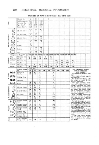
WEIGHTS OF PIPING MATERIALS- 3V 2" PIPE SIZE
1 Schedule No In Std. .318 xxs i i 1 i
80
40
xs
IV-,ignation
Wall
,t>36
Thi< kru'st,
.226
Pipe— I bs Ft 9.11 12.51 22.85 - t , , ,
Water -Lbs Ft 4.28 3.85 2.53
6.4 8.7 15.4
1 R <W J 1-lbott .9 .9 .9
4 3 5.8
s R «»0 i Ibow .6 .6
<fl t.t-'
CJ
3.3 4 4 7.5 I j j ,
1 R 45' 1 Ibow .4 i - i -
1 y 12.6 20 f •" T
Fee t) 9 1 1 1 -i i i
22
I aterul 1.8 J !
31 4.1 6.9
Redtu <-r 3 .3 .3 i
2 1 2.8 5.5
<'ap 6 .6 .6 ]
i
Temperature Range °F to 260* J60-360 360-440 440-525 525-600 600-700 700-800 800-900 [900-1000 , } .
85% Thickness In. l!^j 15£ IH 2 2J4
2 Magnesia Lbs/ Ft J .70 1.70 2.90 425 4.65 i . _ J . 1
2f Combma- Thickness In. 2% 2'»f6 3 *« 1 1 1 ,
3 tlon Lbb, Ft 7.8 7.8 102 . 'H - i t
1
Calcium Thicknejss- in. 1 1 1H l?/ 2 2 2 2 A 3 3 1 |
Silicate Lbi.Ft 1.06 1.06 1.86 1.86 2.75 2.75 3.75 4.88 4.88- f "1"""
Cast Iron Steel
Pressure Rating SEE GENERAL NOTES
pai 125 250 150 300 400 600 900 1500 j 2500 FOR MATERIALS
NOT
SHOWN
21
13
13
Screwed or 1.5 1.5 1.5 27 All weights are shown in bok
Slip-On
1.5
H.ANGES Welding Neck 1.5 28 V- per linear foot. of steel pipe is
12
weight
The
1,5
14 28 For Boiler Feed Piping, adt
water
Lap Joint 1.5 1.5 1 the weight of pipe. to the
weight of steel
14 23 15 35 The pipe covering thick-
Blind 1.5 1.5 1.5 1.5 nesses and weights indicate the
average conditions per linear
35 56 49 82
3:5 /d ] foot arid include all allowances
S R 90° rClbow 4 4.1 4 4.3
for wire, cement, canvas, bands
40 62 54 and paint. The listed thick
I R 90 Elbow 4.4 4.4 4.4 ness of combination covering ia
a *s the sum of the inner and the
M 7%^ 31 51 39 75 outer layer thickness
a / > 45 Elbow 3.6 3.7 3.6 3.9 Pipe covering temperature
5 «e4 ranges are intended as a guide
54 86 70 133 only and do not constitute
Tee 6 6.2 6 6.4 a recommendation for spei-ifu
thickness of materials,
Flanged Bonnet 82 143 88 201 To find the weight of cover-
Gate 7.1 7.5 4,1 4.9 ing on Flanged Fittings, Valves
Flanged Bonnet 74 137 99 160 or Flanges, multiply the weight
(lightface
Globe or Angle 7.3 7.7 4.3 4.9 i factor weight per foot subscript) bv
the
of covering
Flanged Bonnet 71 125 54 123 ! used on straight pipe.
Check 7.3 7.7 4.3 4.9 •All Flanged Fitting, Flangw
w
•L~~' ""fi i Pressure Seal m ~ Valve arid Flange weights inrinde
proportional
weight of bolts
the
l^^~4& / FSonnet 4 fate or studs required to make up al
KD Pressure Sea! i joints. Iron Valve weights
"Cast
Bonnet — Globe
Stee
i *( )ne Complete 3.5 65 3.5 i are for weights are valves. welding
flanged
for
Valve
end valves.
Flange Joint