Page 250 - Estimators Piping Man Hour Manual
P. 250

Section Eleven—TECHNICAL    INFORMATION       225

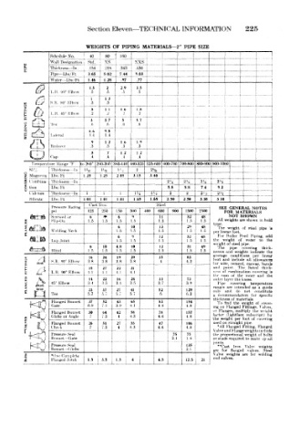
                       WEIGHTS  OF  PIPING  MATERIALS—2"  PIPE  SIZE
             Schedule No.  40  80  j  160  1      _   j
             Wall  Designation  std  \'S  \XS
     H
             Thickness— Tn .  ,  1 54  218  343  i  ;-           -I
     £                                                                      1
             Pipe—Lbs/Ft  j  ?  65  5.02  7.44  9 03           1
                                                               t-
             Water--Lb*/n  1  46  1  28  97  .77               i
                                                                   [
                             2   2 9  * 5
             L.H. W Elbow  '.5 5  .5  .5  .5
                                                                   1
                        1   1 3
             S.H. 90°  Klbow  .3  .3
     0  ~~v                                    ~  -  - • ;
                            1 1  1.6  1  8
             L.R. 45" F.lbow  .2  '->  .2
                                                                            ^
                            3,7  5   5.7
             Tee        .r>  .f.  ,ti  ti
     Z  WJ^J                                                 •  •  -  I  -
     3  J^\             6.6
             Uteral
                            li-                                i
                        9   1 2  1 6  1.9                          1
             Reducer    .3   .3  l .3  .3
                                                               1  -  1-
                        .5   .7  1.2  1 2
       V^tot**  Cap     .4   .4  ,4   .4
                                                 i   , i
                   :
       Temperature  Range 'F  |to  2(iO° 2BO-300  1 3 W-440 440-525 526-KOO  rtOO-700 700-800 800-900(900-1000  1
             Thickness --In.]  l', 2  ''a!  L~ -  2  2-^2  1
                                P
     SE  Mrtgnrsia  Lhs/Ft  1 1.25  1.25  j  2.05 "~3~i!T~" 3 40
                                                    3
                                               !
     g  (,'onibma- |_Tr.irk!ies«~In.         i  2' -4  2 -«,  3' t  t  35,  ,
     §  t,i<m  Lbs/Ft                        [  5.8  5.8  7.4  1  9.2  I
       C'aleium  ^Thickness— In.  1  1  1  i  }-i  l'-i  2  2  '  _i_  2  1
       Silicate  Lhs/i''t  I  1.01  I  01  1.01  1  69  1.69  2.50  2.50  3  38  j  3  38
                        Cast Iron          Steel
             Pressure  Rating                                SEE GENERAL  NOTES
                       125  250 J  150  300  400  600  900  1500 I  2500  FOR  MATERIALS
       i^sisS                   6   9       11          48      ' VOT  SHOWN
     M                  6  1                                 All  we ghta are ihown  in  bold
            1  Slip-On ° "  "  1.5  1.5  1.5  1.5  1.5  1.5  type
                                6   10      13      ^   48"  The  « eight  of  stetl  pipe  is
             Welding  Neck      1.5  1.5    1.5     1.5  1  ',
            "    " '"                 L_  J                 per hnea r  foot
                          -                                  For
                                6                   32  48     B »iler  Feed  I tpmg,  add
             Lap Joint          1.5         ,'i     1.5  1  5  the  weif;ht  of  water  to  the
                                   — — *•-                  weight o steel pipe
                        6   10  4.8  10             31  49   The  pipe  mvenng  thjik-
             Blind      1.5  1.5  1.5  1.5  1.5     1.5  1.5     d  weights  uulieate  the
                        16  24  19  29      35  !   83      a  v erage conditions  {tor  linear
                                                              and include
     0 X  l**^*.       3.8  3.8  3.8  3.8   4  I    4.2     foot  wire, cement  all  allowances
         / ,1l S.R. '»" Elbow
                                                            for
                                                                     canvas,
                                                                          bands
     i   /:! L.R.  90" Elbow  1.1  4.1  4.1  4.1            ind  pal it  The  listed  thick- is
                                22
                            27
                        18
                                    31
                                                                ombttutrion
                                                                       covering
                                                                   the
                                                                     inner
     a   fc             14  !  22  16  24           73      t hi  sum of tht< knehs  and  the
                                                            out, r layer
     a   />  45" Elbow  3.4  3.5  3.4  3.5  3 7  I  3.9      P.pe  covering  temperature
                                            3
     z  »s£                                                 range--  a e  intended  as  a  guide
                        23
                       5.7i £   5   41      52      129          i  do  not  constitute
             Tee                    5,7     6       6.3     a  rei om nendation  fur  specific
                                                            thickness of  materials
                                    65
                                                    154
                                            83
                            52
                        37
                                43
                                  [
             Flanged Bonnet
      KlQ    Gate '    6.9  7.1  3.9 | 4.1                  mg on  F anged  weight  of (over-
                                                                  the
                                                             To fin J
                                                                         \
                                                                    F«ttirig<!
                                                                          then,
                                                            or  Flang •^, multiph  the  weight
                                    58
             Flanged or  Bonnet  30  64  42 4  !  4.3  4.4  157  1  factor  (1 giitface  lubsiript  1  !>y
                                            78
     i       Check  Bonnet  26  7.3  27  4.3  4.4 47  | 1  106  the •All  F tinged  foot  of o\> ring
             Globe
                            7.3
                                                    4.8
                  Angle
                                                                  per
                                                              weig it
                                                                        i
                                                            used on stralght pipe
                                    59
                            51
             Flanged
                                                                    Fitting
                                                                         Hinged
                        7
                                4
                                                    4.8
                                                            \alveam ^ Ltnge wi l(i;ht^ inrlude
                  Seal
         sj Pressure
                                                75
                                                                          holts
             Bonnet— Gate                       2.1  75     the  propcirtionul  weight  of  tp all
                                                            or studs squired to make
                                                    1.4
                              I   i                         joints
             Pressure Seal                          135      **C'ast Iron  Valvr  weights
             Bonnet --Globe                         2.1     are  for flanged  vaKee  Steel
     5      1 'One Complete                                 Valve  v, "•ights  are  for  welding
                                                            end
     ^       Flanged Joint  1.5  3  !  s     5      12.5  21  valvt38.
                           _ :_ _i_l: _Ll  L  i*- _l
   245   246   247   248   249   250   251   252   253   254   255