
Page 254 - Estimators Piping Man Hour Manual
P. 254
Section Eleven—TECHNICAL INFORMATION 229
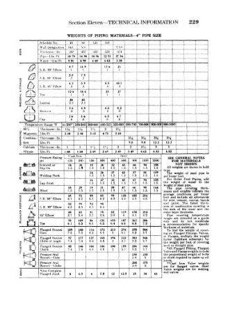
WEIGHTS OF PIPING MATERIALS-4" PIPE SIZE
.Schedule No 40 HO 1.20 ll'iO _ 1 L J
\Vlll I)<»»Kii'itloii Std. \^ \\s - i- J
S HIM knev, in 237 337 437 531 d71 4 4 j
£
i'UM 1 bs rt 10 79 1498 1896 22 51 27 54 1
. -
\\aU-r -I lis/Ft 5.51 4 98 4 48 402 338 1
t
8.7 11 9 17.6 21 . i . i
L H 00 1" llMm I 1 1 l l !
ft 79
S K 10 I lt,ow .7 i
43 5.9 8.5 10 1
L R 4V Kllwm * 4 .4 .4 ] i
126 16 4 23 27 - ! t
Tee 1 1 1
r UraLoJ
30 45
i Kjb Lateral 2.1 2 1 ; I
T ' " ~ r !
36 6.6 8.2
Kedu. ct .3 *3 9 3 3 i
2.6 34 65 6.7 , i
Cap ti .6 6 b
Ternperat ure Hnuge °F to 260° 5860-3ttO 360-440 440-525 525-600 600-700 700-800 800-900 900-1000 ,__:.. i
Tin, km 88— In IV, 1>2 2 21,4
85* (
a „ l> 8
f. Magtipsia Ibs/Ft 210 2.10 3.15 4 75 5 10 —, — | 1
s
* Combma- Thw knees— In 3'ii 3' it 3 /Ui 3 -l8 1 j
9
8 *«>» Lbs, Ft 9 8 98 122 12.2
Calcium Thickness —In 1 1 I'/ 1'i 2 2 2»4 3 3 -
Silicate Uw Ft 1 60 1 60 2 49 249 349 349 462 603 6.03 i . i
Cast Iron Steel
SE E GENERAL NOTES
psi 125 250 150 300 400 (>00 000 1500 2500 1 FOR MATERIALS
NOT
SHOWN
26
16
15
66
26
32
Screwed or 1.5 1* 1.5 1.5 1.5 43 1.5 94 158 All weights are shown in bold
FLANGES Welding Neck 1 5 26 5 1.5 43 1 5 1 5 159 tvpe. The weight of steel p.pe is
1.5
1.5
Khp-On
1 5
57
81
37
14
"
1.5
1 5
1
foot
per linear
16 27 33 45 ~ l 67 94 155 For Boiler Feed Piping, add
Lap Joint 1.5 I 5 1.5 1 5 1.5 1.5 1.5 the »eight of water to the
weight of steel pipe,
18 29 19 31 39 47 66 90 164 The pipe covering thiclc-
Blind 1 5 1 5 1 5 1.5 1.5 1 5 1.5 1.5 1 5 ne&ses and weights mdleat* the
average conditions per hnear
45 72 59 85 99 128 185 254
S R 90° Flbow 4 1 4.2 4 1 4.2 4.3 4.4 4.5 4 8 foot and inelude all allowances
for wt re r cement, canvas bamto
C /•" is 52 79 72 98 and j amt. The !H>ted thick-
L R 90° Elbow 4.5 4 5 4 r T 4.5 ness o combination covering is
the sura of the inner and the
40 65 51 78 82 170 214 outer ayer thickness,
Pipe
O / Tlfe* 16° Elbow 3.7 38 37 3.8 39 4 4 1 4 2 ranges are covering temperature
^ 5 Tee 6.1 109 6.1 121 153 187 262 386 only reccmmendation for constitute
intended
as
a
guide
70
86
and
not
do
7.2
6.6
6.8
6.4
6.3
6.3
a
specific
thickness of materials,
Flanged Bonnet 109 188 114 173 213 274 378 566 To ind the weipht of rover-
7.2 7.5 4.2 4.5 5 5.1 5.3 5.7 ing on Flanged Fittings, Valves,
97
Flanged Bonnet 7.4 177 127 168 194 222 383 546 or Flanges. multiply the weight
farter (lightface
by
subscript)
5.7
4.8
5
5.3
Globe or
4.4
7.8
Angle
5.1
wt ight
per
foot
••VALVES (.'heck 7.4 146 104 146 180 159 256 344 used on straight pine.
the
of covering
Kiait&ud Bonnet
SO
•All Flanged Fitting, Flanged
5
5,1
4.S
7.8
4.4
5.7
5.3
Pressure Sea! ! 230 235 Valve ind Flange weights include
bolts
the pruportional weight of
Bonnet- -Gate 2.8 3 or stucs required to make up all
joints.
Pressure .S< al T 260 375 •»cast Iron Valve weights
Bonnet- Globe 2.8 3 are fc r flanged valves. Steel
Valve weights are for welding
'One Complete end vaJve*. .
1 Flanged Joint 4 6.5 4 7,5 12 12.5 25 34 61