Page 249 - Estimators Piping Man Hour Manual
P. 249

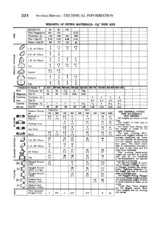
Section Eleven—TECHNICAL INFORMATION

                       WEIGHTS  OF PIPING  MATERIALS—1V 2" PIPE  SIZE
      1       Schedule No.  Std.  .200  .281  XX8         zj             j j |
                                  160
                             80
                         40
                             xs
              Wall Designation
              Thickness — In.
                        .145
                                      .400
              Pipe— Lb»/Ft
                                                                         1-
              Water— Lbi/Ft  2.72  3.63  4.86  6.41                  _±_
                                  .61
                             .77
                                      .41
                         .88
         &    L.R,  30° Klbow  .8 .4  I.I  1.4  1.8
                                                                        ~
                                  .4
                                       .4
                              .4
                                                      ~j"  -
                         6    .7
              8.R. 90° Elbow  .3                       j
                              .7  .8   1
              L.R.  46°  Elbow  j  !a  ___1  .2  .2
                              .2
      la      Tee        2 6  .6  3.1  3.7
                                  .6
                                       .6
                         4.3  5.8
              Lateral    1.3  1.3
                                                       |  _
                         .6   .7  .9  1.2
              Reducer    .2   .2  .2   .2
                         .4   .5  .7   .7
              Cap        .3   .3  .3   .3
            1
        Tempera ure Range *F  to  200°  iJ60-360 360-440 440-525 525-600 600-700 700-800 800-900 900-1000
      o 85%   Thickness— In,  J-j  H  m  2  1'%                          f   1
      Z  Magnesia Lbs/Ft  .85  .85  1.75  2.65  2.45
      u  Combina- Thickness- -In.               2    2    2   2          H
      £3  tion  Lbs/Ft                         4.2  4.2  4.2  4.2
       Calcium  Thickness- -In.  1  1  1  1  1H  Ui  2   2H   2U
       Silicate  Lbs/Ft  .88  .88  .88  .88  1.45  1.4S  1.82  263  2.63
              Pressure Rating  Cast Iron    Steel             SEE  GENERAL  NOTES
              p«        125  250  150  300  400  600  900  1500  2500  FOR  MATERIALS
              Screwed or  3.5  7  3.5  8     9       19  31      NOT  SHOWN
              Blip-On   1.5  1.5  1.5  1.5   1.5     1.5  1.5  All weights are  shown in hold
                                                             type.
                                 4   9       11      17  32   The weight  of  steel  pipe  is
              Welding Neck      1.5  1.5     1.5     1.5  1.5  per linear foot.
                                3.5  g       9       19  31   For Boiler  Feed  Piping,  add
      OONVU
              Lap Joint          1.5  1.5    1.5     1.5  1.5  the  weight  of  water  to  the
                                                                  steel pipe,
                        3.5  7  3.5  9       10      19  31  weigh of pipe  covering  thick-
                                                              The
              Blind 90°  Klbow  3.7  1.5  3.7  3.8  3.9  1.5  1.5  nesses and conditions  per  linear
                                             1.5
                                 1.5
                        1.5
                                     1.5
                                                                   weights indicate
                                                                            the
                                                             average
                                 12
                                                     46
                                             26
                                     23
                         10
       FLANGED FITTINGS  45° Elbow  3.4  3.4  35  3.5  3.7   and Pip* r>aint. of  the  inner covering the is
                                                                        allowance*
                                                                  include
                                                                      all
                                                               and
                                                             foot
              S.R.
                                                     4
                                                                      canvas, bands
                                                                re, cement,
                                                                           thick-
                                                                       listed
                         12
                                 13
                                                                    The
                                     24
                                                             ness o ' combination
              L.R. 90° Klbow
                         4
                                     4
                                 4
                                                                m
                                                                         and
                                     21
                                             23
                                 11
                         9
                                                     39
                                                             outer ayer thickness,
                                                                       temperature
                                                                  covering
                                                                        as
                                                                          a guide
                                                                 are
                         17
                                             37
                                 20
                                     30
                                                                   do
                                                                      not
              Tee       5.6     5.6  6.7     5.8     70 6    only and  intended  for constitute
                                                             a
                                                              reccmmendation
                                                                          specific
                                                                ess of materials,
       fO     Flanged Bonnet  6.8    51      4.2     114     ing on Flanged Fittings, of  Valves,,
                         27
                                             71
                                                                          cover-
                                                                     weight
                                                                   the
                                                              To ind
                                     4
              Gate
                                                     4.5
                                                              Flunges, 'multiply
                                                             or
                                                                          weight
                                             46
                                                                      subscript)
      f K)    Flanged Bonnet         40      4 2     111    factor (lightface foot  of the covering
                                                                            by
                                     4.1
              Globe or Angle
                                                     4.5
                                                                   per
                                                                jght
              Flanged  Bonnet        32      33      81      used on straight  pipe.
              Check                 4,1      4.2     4.5      •All Flanged Fitting,  Flanged
                                                                uid Flange weights include
              Pressure Seal                      42  42      the prnportional weight  of bolt*
              Bonnet — Gate                      1.9  1.2    or stut a required to make up all
                                                            jointa.
              Pressure  Seal                                  **Cast  Iron  Valve  weight*
              Bonnet — Globe                                 are  fcr  flanged  valves.  Steel
      i       Flanged Joint  1  2.5  1  3.5                 end va Ives.  are  for  welding
                                                             Valve weights
              *One Complete
                                             3.5
                                                     9
                                                        1  t2
   244   245   246   247   248   249   250   251   252   253   254