
Page 248 - Estimators Piping Man Hour Manual
P. 248
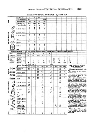
Section  Eleven—TECHNICAL INFORMATION         223

                      WEIGHTS  OF  PIPING  MATERIALS—1%" PIPE  SIZE
     1       Schedule No.  Std.  .191  .250  XX8                    ..__!   ~
                             80
                                 160
                        40
                            xs
             Wall Designation
             Thickness — In.
                        .140
                                     .382
             Pipe— Lbs/Ft
             Water— Lbs/ Ft  227  3.00  3.77  5.21         [
                             .56
                                  46
                                      27
                        .65
                        .6   .8  .9   1.2
             L.R. 90° Elbow  .3  .3  .3  .3
                        .4
             S.R. 90" Elbow  .2                                     !
     lj>     L.R.  45° Klbow  .4 .2  .2 5  .2 6  .8 .2     1
                        1.3  16  1.9  2.4
             Tee        .5   .5  ,5   .5                   I
                        3.4  4.2
             Lateral    1.2  1.2                                        i
                        .5   .5   6   8
             Reducer    .2   .2  .2   .2
                        .3   .4  .5   .6
             Cap        .3   .3   .3  .3
       Temperature Range °F  to  260"  3•60-360 360-440 440-525 525-600 600-700 700-800 800-900 900-1000  !
                                          s
       8S%   Thickness — In  H  X  1'i  2  l' /w                         (
     z  Magnesia  Lbs/Ft  ,80  .80  1 60  245  2 25
     8  Combina- Thickness — In.               2    2    2   2
     Q  won  Lbs/ Ft                           4.1  41  4.1  4.1
       Calcium  Thickness — In .  1  1  1  1  14  l'-j  2  2  2}i
       Silicate  Lbs/Ft  .68  .68  .68  68  1  19  1.19  1.87  1.87  2.68
                        Cast Iron           Steel
             Pressure  Rating                                 SEE  GENERAL NOTES
             psi        125  250  1.50  300  400  I  600  900  1500  2500  FOR  MA TERIALS
      &e£sa  Screwed or  2.5  5  3.5  5      7      13  23      NOT  SSHOWN
     g       Slip-On    1.5  1.5  1.5  1.5  1.5     5.5  1.5  All weights are shown in bold
                                33  6.5      7      12  23  type.  weight of  steei  pipe  is
                                                             The
             Welding Neck       1.5  1.5    1.5     1.5  1.5  per linear foot.
                                                                Boiler
     *68Lm                      35  5       1.5     1.5  22  the For weight  ol Feed water  to  add
                                                                       Piping,
                                                    13
                                             7
                                                                           the
                                1.5
                                                        1.5
             Lap Joint
                                    1.5
                                                            weight of steel  1
                        3.5  5  35  7        7      13  23   The  pipe  P'P*  .  thick-
                                                                    covering
       i^B^|i-Sj( ji  Blind  1.5  1.5  1.5  1.5  1.5  1.5  1.5  nesses  and  wei{ hts indicate  the
       Jr^-lln A
     i   J   S.R. 90' Elbow  3.6    3.7     3.8     3.9     average  condit ions all  per  linear
                                    17
                                                    33
                                            18
                        g
                                                                 indue«
                                                            foot
                                                               and
                                                                        allowances
                                                              wire, cement,
                                                            for
                                                                      canvas, bands
                                                               paint.
                                                            and
                                                                   T ie
                                    13
                        10
     i   /?  L.R. 90° Elbow  3.9    3.9                     the  sum combin ition listed and thick-
                                                            ness
                                                               of
                                                                       covering is
                                                                   tha
                                                                 of
                                                                            the
                                                                     inner
                        7           15      16      31      outer layer thic kness.
             45° Elbow  3.3         3.4     3.5     3.7      Pipe  covering  temperature
                                                            ranges  are tntended  as  a  guide
                        13          23      28      49      only  and  do not  constitute
     1 Q T«e            6.4         5.6     5.7     5.9     a thickness of materials. for  specific
                                                             recommenda ;ion
       f<3   Flanged Bonnet         3.8             4.4     ing on  Flanged Fittings, VaKes,
                                    34
                                                    95
                                                                          cover-
                                                                        of
                                                             To find the weight
             Gate
             Flanged Bonnet                                 or Flanges, mu tiply  the  weight
                                                            factor
                                                                      subscript)
                                                                            by
                                                                (lightfai»
       KC    Globe or Angle                                 the  weight per foot  of  covering
     H
             Flanged  Bonn<-t       21                      used on straightpipe.
             Check                  4                        •All Flanefd Fitting, Flanged
                                                            Valve and Flan| e weights include
             Pressure  Seal                     38  38      the  proportion)1 weight of bolts
             Bonnet — Gate                      1.8  1.1    or studs requireid to make up all
                                                            joints.
             Pressure  Seal                                  **C»st  Iron Valve  weights
             Bonnet— Globe                                  are  for  flanged  valves.  Steel
                                                            Valve  weights are  for  welding
     3       "One Complete                                  end valves.
     i       Flanged Joint  1  2  1  2       2       6   9